


The pressure vessel consists of a cylindrical main tank, and an inlet and an outlet at each end of the tank, as shown below:
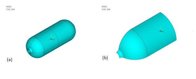
The tank wall has a composite construction of one homogeneous aluminum alloy liner and four T800/EPOXY fiber-reinforced layers. The inlet and outlet are made of aluminum alloy only. Due to the symmetry, only one-eighth of the entire geometry is modeled (shown by (b) in the above figure).
For this problem, the composite wall is modeled as two distinct components:
One isotropic matrix component containing the liner and all bonding material (resin) in the reinforced layers
Another fiber component representing all reinforcing fibers.
The modeling approach described allows one to independently study the failure limits of the matrix and fiber components based on their own strength characteristics.
The shell element SHELL281 is used for meshing the matrix component.
The SHELL281 mesh is shown by (a) in the following figure:
The layup of the matrix material is defined using shell sections. Following are the section properties, including material IDs, layer thickness, material orientation (irrelevant if the material is isotropic), and the number of layer integration points:
| Section | Layer Thickness | Material ID | Material Orientation Angle | Integration Points |
|---|---|---|---|---|
| 1 (main tank wall) | 1.9e-3 | 1 | 0 | 3 |
| 0.1e-3 | 2 | 0 | 3 | |
| 0.1e-3 | 2 | 0 | 3 | |
| 0.1e-3 | 2 | 0 | 3 | |
| 0.1e-3 | 2 | 0 | 3 | |
| 2 (inlet / outlet wall) | 1.9e-3 | 1 | 0 | 3 |
For proper internal pressure application, the shell sections are offset to the bottom (SECOFFSET).
It is assumed that the fibers in each reinforced layer have a unique cross-section area, material property, spacing, and orientation; therefore, a smeared reinforcing approach is used. With smeared reinforcing, the fibers are represented by an equivalent homogeneous layer (instead of the fibers being modeled individually). The smeared approach allows for better computational efficiency. The smeared reinforcing element used is REINF265. The fiber properties (material, cross section area, spacing, orientation, and location) are defined via the reinforcing section using the smear subtype (SECTYPE,REINF,SMEAR), as follows:
| Reinforcing Layer # | Material ID | Fiber Cross-Section Area | Distance Between Two Adjacent Fibers | Fiber Orientation Angle | Layer Location in Base Element |
|---|---|---|---|---|---|
| 1 | 3 | 0.5e-4 | 1.0 | 45 | 2 |
| 2 | 3 | 0.5e-4 | 1.0 | -45 | 3 |
| 3 | 3 | 0.5e-4 | 1.0 | 45 | 4 |
| 4 | 3 | 0.5e-4 | 1.0 | -45 | 5 |
The expanded solid display (/ESHAPE) of both SHELL281 (shown in translucency) and the embedded REINF265 elements is shown by (b) in Figure 9.2: COPV Mesh.