


The following topics concern the computational fluid dynamics (CFD) modeling of this problem that have been carried out on the bladed disk in order to retrieve the unsteady flow pressure:
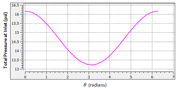
The unsteady flow pressures which act on the fan blade are required for the structural analysis. The unsteady fluid calculations are carried out using Ansys CFX. The unsteady pressures on the blades arise due to the one per revolution distortion signal at the inlet as well as the rotation of the blades in a pressure field. The expression used to generate the 10% inlet distortion is:

This expression is plotted in the following figure:
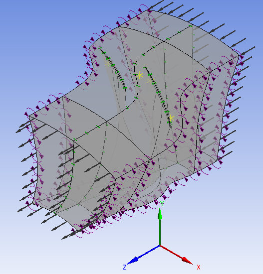
For the CFX analysis only two blades are considered, as shown below:
The Fourier Transformation Inlet Disturbance method is used in this analysis. This method belongs to the Transient Blade Row (TBR) family of transient methods for obtaining a full wheel representation of the solution data by solving on a few passages per blade row, thereby providing substantial savings in solution time. The Fourier Transformation Inlet Disturbance method used in this study employs a Double Passage strategy, where the Fourier coefficients are collected on a sampling plane at the interface between the two rotors. Though this increases the domain size, it has been found to provide a faster convergence than the single passage method.
A steady-state solution is performed prior to the transient analysis, and the results from the steady-state solution are used to provide a good initial condition for the transient case. The transient solution is carried out for a few revolutions of the blade until the periodicity of the solution is achieved. The real and imaginary pressures on the blade surfaces are exported at the required engine order in a .CSV format, which is read into Ansys Mechanical for carrying out the forced-response analysis.
The convergence of the solution is monitored by creating monitor points at important locations in the domain. One such example is shown below:
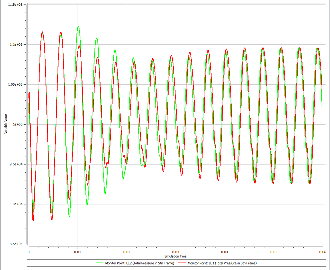
The solution is deemed to be converged when the monitor plots attain periodicity. In addition, it is also important to check the conservation of mass, momentum, and energy before accepting the final solution.
The unsteady pressure data has been calculated using two blade rows in this analysis. This data is easily expanded to obtain the full wheel variation of pressure using CFD-Post, as shown in the following figure:
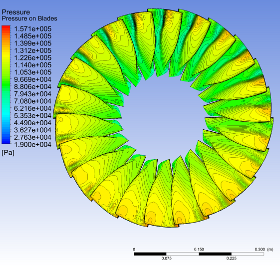
These unsteady pressures define the aerodynamic forcing due to the fluid forces. These aerodynamic data can be written to a file in the .CSV format at a specified engine order to perform further analysis using Ansys Mechanical.