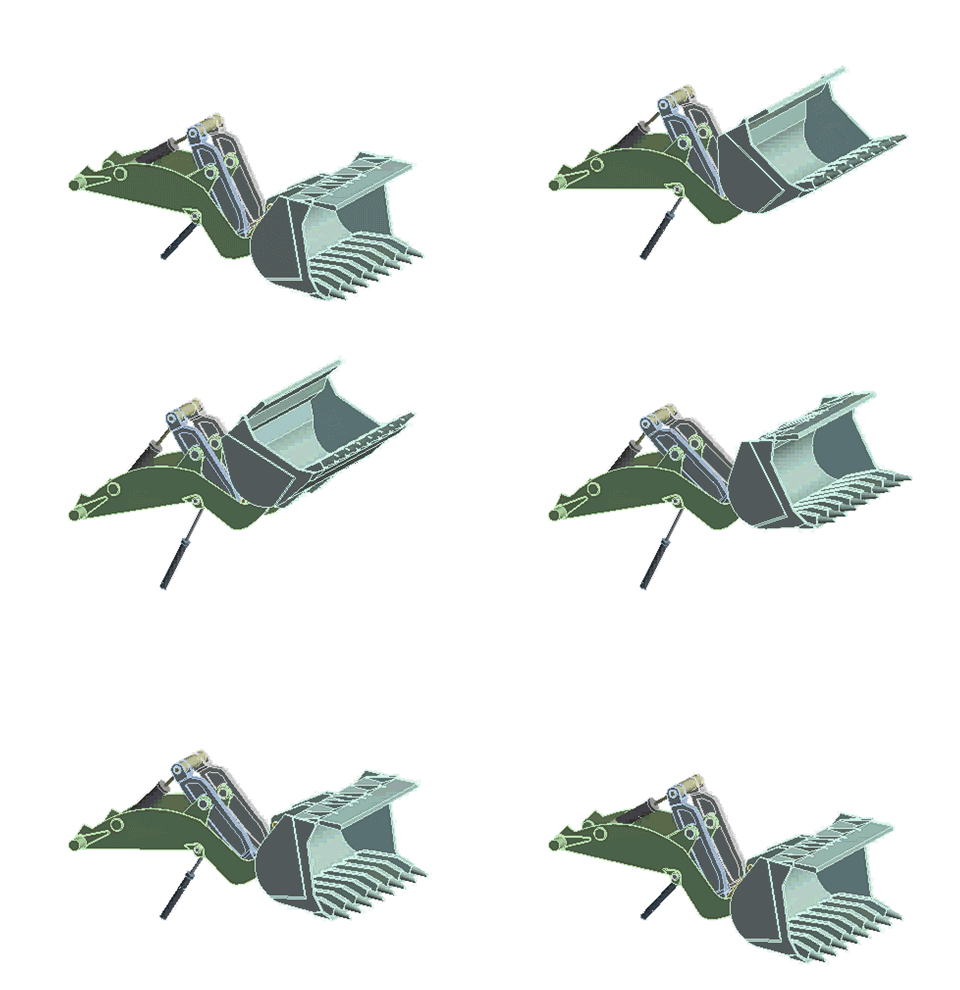
The following animation (generated in Ansys Workbench) shows the motion of the digger-arm assembly:
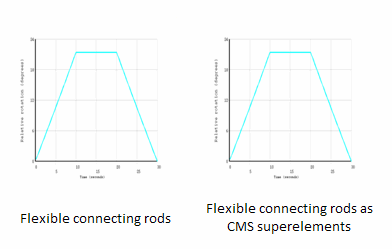
The following figure shows the rotation of the frame with respect to ground for the two transient dynamic analysis cases. The motion of the frame (due to the activation of the piston-cylinder assemblies) is the same in both cases.
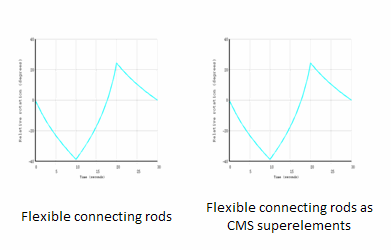
The following figure compares the relative rotation of the bucket with respect to the frame for the two analysis cases. The rotations in the both cases are nearly identical.
Both relative-rotation figures shown above indicate that the kinematic behavior of the digger-arm assembly, modeled as a rigid/flexible combination, exhibit the same behavior. When flexibility is involved in an analysis, modeling the assembly as though it consisted of rigid parts and ensuring that the joints are defined correctly using the rigid dynamics solver, allows the engineer to focus on other issues.
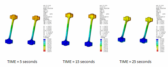
The stresses and deformation fields can be evaluated when the connecting rods are made flexible. The following figure shows the deformation plots (USUM) of the connecting rods when the rods are modeled as flexible:
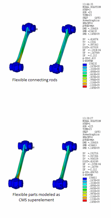
The following figure shows the equivalent stresses in the connecting rods when the rods are modeled using SOLID185 elements and as CMS superelements, respectively.
The time point is at 25 seconds (load step 3, substep 25). The equivalent stress plots show good agreement with each other.
The following table shows the CPU time comparisons between the two analysis cases.
| Flexible and Rigid Parts | CMS and Rigid Parts | |
|---|---|---|
| Total degrees of freedom | 2874 | 702 |
| Total iterations | 489 | 436 |
| Generation time (with original database saved) | --- | 2.38 seconds |
| Use pass time | --- | 46.8 seconds |
| Total CPU time (including full-model save, generation pass, use pass, expansion pass, and results processing) | 372.68 seconds | 78.06 seconds |
In all cases, shared memory parallel with two CPUs is used. The results are reported for a 64-bit Linux system.
The table and the other results discussed highlight some essential analysis considerations:
It is worthwhile to verify the kinematic behavior of the multibody system by assuming all parts as rigid, as the time and resources required for the rigid analysis are small. You can use the rigid dynamics solver (available in Ansys Mechanical) to do so.
Modeling the flexible bodies using CMS superelements results in significant time savings.
Analysis of the assembly when the flexible part is modeled with 3D finite elements necessarily requires more time due to the increased number of degrees of freedom. Such an analysis, however, should be performed only when the flexible part undergoes large deformations, either due to nonlinear material behavior or to nonlinear geometric effects.


