The following example shows the computation of pressure distribution in a three-lobe journal bearing. The input clearance as a function of the angular position can be downloaded here.
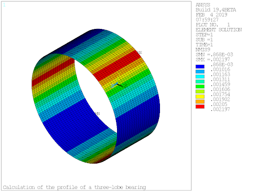
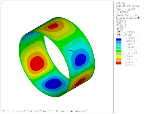
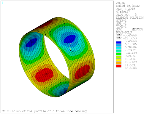
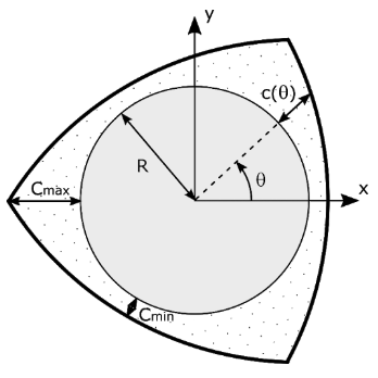
The fluid pressure and thickness distributions are computed in a static analysis. The rotor is a cylindrical shaft rotating at 200 rad/s whose equilibrium position in the stator is (-4.2, -35.0) x (1x10-6) m. The bearing cross-section geometry consists of three lobes as shown in Figure 7.45: Three-Lobe Journal Bearing Cross-Section Geometry. The clearance is defined as a function of angular position (θ) as:
 | (7–1) |
Where Cmax and Cmin are the maximum and
minimum clearance, respectively, and  is the angular position of the lobe center i,
i ∈ {1,2,3}.
is the angular position of the lobe center i,
i ∈ {1,2,3}.
The bearing fluid film is modeled with FLUID218 elements with node-based clearance following Equation 7–1 in element real constants.
The bearing properties are as follows:
Length: 0.1 m
Shaft radius: 0.1 m
Fluid viscosity: 0.12 Pa·s
Minimum clearance: 9 x 10⁻⁴ m
Maximum clearance: 22 x 10-4 m
/title,Calculation of the Profile of a Three-lobe Bearing
/out,scratch

!============
! PARAMETERS
!============

pi  = acos(-1)
eps = 1e-6 ! accuracy for node selection

! Three-Lobe Bearing Parameters
! ------------------------------
bearingLength = 0.1         ! length of the bearing
Nlobe          = 3          ! number of lobes
Cmax          = 0.0022      ! maximum clearance (at lobes edges)
Cmin          = 0.0009      ! minimum clearance (at lobes center)
alpha         = 2*pi/Nlobe  ! arc angle of the lobes
offsetRatio   = 0.5         ! angular offset ratio
Dclear        = Cmin - Cmax ! delta of clearance

! Shaft (Stator) Parameters
! -------------------------
shaftRadius   = 0.1         ! radius
shaftPosX     = -4.2e-6     ! X-position inside the bearing
shaftPosY     = -3.5e-5     ! Y-position inside the bearing

! Fluid Properties
! -----------------
fluidVisc = 0.12            ! viscosity
fluidDens = 1000            ! density

! Meshing Parameters
! ------------------
NeltCirc   = 200            ! number of elements along bearing circumference
NeltLength = 20             ! number of axial elements

! Loading
! -------
omg = 200 ! rotational velocity

!======================
! READ CLEARANCE INPUT
!======================
*dim,clearanceArray,array,NeltCirc+1,2
*vread,clearanceArray(1,1),clearanceInput,txt,,JIK,2,NeltCirc+1
(F5.1,F10.8)

!===============
! PRE-PROCESSING
!===============
/prep7

! Geometry
! --------

! Create shaft for virtual use in FLUID218 (suppressed at the end)
cylind,0,shaftRadius,0,bearingLength,0,90
cylind,0,shaftRadius,0,bearingLength,90,180
cylind,0,shaftRadius,0,bearingLength,180,270
cylind,0,shaftRadius,0,bearingLength,270,360
NUMMRG,KP

! Material Properties
! -------------------

! Shaft (virtual parameters)
mp,ex,1,2e9
mp,prxy,1,0.3
mp,dens,1,8000

! Fluid parameters
mp,visc,2,fluidVisc
mp,dens,2,fluidDens

! Meshing
! -------

! Mesh the shaft
	et,1,solid185

	csys,1
	! basis circumference
	lsel,s,loc,z,0
	lsel,a,loc,z,bearingLength
	lsel,r,loc,x,shaftRadius
	lesize,all,,,NeltCirc/4

	! basis interior lines
	lsel,s,loc,x,shaftRadius
	lsel,inve
	lsel,r,loc,z,0
	lesize,all,,,NeltCirc/4

	lsel,s,loc,x,shaftRadius
	lsel,inve
	lsel,r,loc,z,bearingLength
	lesize,all,,,NeltCirc/4

	! longitudinal
	lsel,all
	lsel,u,loc,z,0
	lsel,u,loc,z,bearingLength
	lesize,all,,,NeltLength
	csys,0

	! sweep mesh
	allsel
	type,1
	mat,1
	vsweep,all

! Mesh bearing fluid
	et,2,fluid218
	type,2
	mat,2

	! loop over angular position
	*DO,i,1,NeltCirc,1
		etid    = i + 1

		! create real constant
		r,etid,0,shaftRadius,shaftPosX,shaftPosY
		rmore,,clearanceArray(i,2),clearanceArray(i+1,2),clearanceArray(i+1,2),clearanceArray(i,2)

		! create elements
		real,etid

		! select elements wrt angular position and mesh
		csys,1
		nsel,s,loc,x,shaftRadius
		nsel,r,loc,y,clearanceArray(i,1)-eps,clearanceArray(i+1,1)+eps
		esln
		esel,r,cent,y,clearanceArray(i,1),clearanceArray(i+1,1)
		esurf
		csys,0

	*ENDDO

! Clear solid elements
	allsel
	vclear,all
	etdele,1
	numcmp,all

! Boundary Conditions
! --------------------
nsel,s,loc,z,0
nsel,a,loc,z,bearingLength
d,all,pres,0               ! zero pressure at both ends

allsel
save
finish

!===================
! SOLUTION PROCESSOR
!===================
/solu
antype,static
omega,,,omg
solve
finish

!=================
! POST-PROCESSING
!=================
/post1
set,last
allsel

*get,eltNum,elem,,count

! Get Maximum Pressure
! --------------------
nsort,pres,,1
*get,maxPressure,sort,0,max
*get,maxPressureNode,sort,0,imax
csys,1
maxPressureAngle = ny(maxPressureNode)
csys,0

! Get Minimum Film Thickness
! --------------------------
etable,H,nmisc,1
esort,etab,h,1
*get,minThickness,sort,0,min
*get,eltMinThickness,sort,0,imin
*get,nodeMinThickness,elem,eltMinThickness,node,1
csys,1
minThicknessAngle = ny(nodeMinThickness)
csys,0

! Get Total Forces
! -----------------
ielem  = 0
forceX = 0
forceY = 0
*DO,i,1,eltNum
   ielem = elnext(ielem)
   *GET,CON,elem,ielem,NMISC,11
   forceX = forceX + CON
   *GET,CON,elem,ielem,NMISC,12
   forceY = forceY + CON
*ENDDO

! Get Attitude Angle
! ------------------
angLoad   = atan(forceY/forceX)*180/pi
angCenter = atan(shaftPosY/shaftPosX)*180/pi
angAtt    = angCenter - angLoad

! Results Plots
! -------------

/show,png,rev
/view,,1,1,1

! Fluid thickness
/edge,,1
plesol,nmisc,9
/edge,,0

!Nodal pressures
plnsol,pres

! Fluid velocities
/edge,,1
rsys,solu
plesol,PG,X    ! tangential
plesol,PG,Y    ! axial
rsys
/edge,,0

/out,
/com,* ========================================================
/com,*                      =========
/com,*                       RESULTS
/com,*                      =========
/com,*
/com,* Minimum thickness:          %minThickness% m
/com,* Minimum thickness angle:    %minThicknessAngle% deg
/com,* Maximum pressure:           %maxPressure% Pa
/com,* Maximum pressure angle:     %maxPressureAngle% deg
/com,* Total force in X direction: %forceX% N
/com,* Total force in Y direction: %forceY% N
/com,* Attitude angle:             %angAtt% deg
/com,*
/com,* ========================================================
/out,scratch
* ========================================================
*                      =========
*                       RESULTS
*                      =========
*
* Minimum thickness:          8.678740123E-04 m
* Minimum thickness angle:    -118.8 deg
* Maximum pressure:           63682.2737 Pa
* Maximum pressure angle:     -140.4 deg
* Total force in X direction: -27.6204842 N
* Total force in Y direction: -25.9966112 N
* Attitude angle:             39.8919837 deg
*
* ========================================================