This example demonstrates the static analysis of a compressor multistage system. Specifically, it demonstrates the following key points:
Static analysis of a multistage system
Use of only base sectors for static, HI = 0 cases
Axial multistage modeling with more than 2 stages
Mismatched interstage boundaries requiring mapping
Offset cyclic edge starting points
Expansion
The example problem is presented in the following sections:
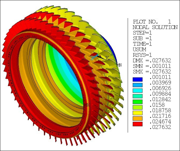
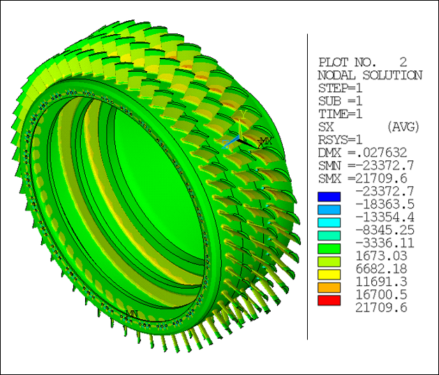
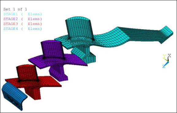
The multistage system consists of 4 axially aligned cyclic stages merged at 3 interstage boundaries. There are 3 blade rows and a rim modeled using SOLID186 and SOLID187 elements as shown in Figure 7.1: Compressor Model with 4 Axial Stages . The model is fixed along the hoop of the upstream hub. The stages have the following sector counts:
| Stage | Sector Count |
|---|---|
| 1 | 43 |
| 2 | 48 |
| 3 | 54 |
| 4 | 30 |
The finite element models of the four stages in axial alignment are shown below.
The following table describes the key steps and related commands used for the example analysis. See Input for the Analysis for the detailed command listing.
| Step | Description | Mechanical APDL Commands |
| 1. | Create base sector for each stage. | CDREAD,... |
| 2. | Create stage components for each stage. | CM,... |
| 3. | Create sector low/high edge components for each stage. | CM,... |
| 4. | Create stages and apply cyclic constraints for harmonic index 0. |
MSOPT,NEW,... CECYCMS,... |
| 5. | Set analysis type (static). | ANTYPE,STATIC |
| 6. | Apply multistage constraints. | CEIMS,... |
| 7. | Apply other boundary conditions. | D,.... |
| 8. | Apply external loading in the form of rotational velocity. | OMEGA,... |
| 9. | Solve the analysis. | SOLVE,... |
| 10. | Enter POST1 postprocessor. | /POST1 |
| 11. | Set expansion parameters to expand all stages and sectors. | MSOPT,EXPA,ALL,ALL |
| 12. | Read results, expand database and expand results. | SET,... |
| 13. | Plot expanded displacements. | PLNSOL |
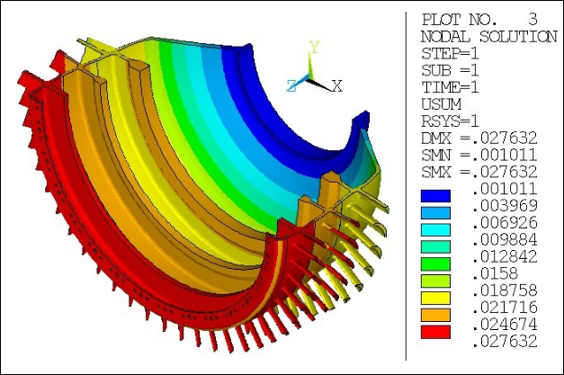
| 14. | Define cutting plane. | /CPLANE,... |
| 15. | Plot same expanded displacements with different cut view. | PLNSOL |
Download the zipped .cdb files used for this example problem.
/batch,
/com ===============================================================
/com Multistage static analysis - compressor
/com ===============================================================
! define stage information
!--------------------------
NumStages = 4 ! Number of stages
NS1 = 43 ! Stage1 number of sectors
NS2 = 48 ! Stage2 number of sectors
NS3 = 54 ! Stage3 number of sectors
NS4 = 30 ! Stage4 number of sectors
HI1 = 0 ! Stage 1 harmonic index
HI2 = 0 ! Stage 2 harmonic index
HI3 = 0 ! Stage 3 harmonic index
HI4 = 0 ! Stage 4 harmonic index
! create multistage components
!-----------------------------
*do,iter,1,NumStages
! Read in stages in reverse order
filenum=NumStages-Iter+1
cdread,db,Stage%filenum%,cdb
! Create stage components
cm,_Stage%filenum%_base_elm,elem
nsle
cm,_Stage%filenum%_base_nod,node
cmsel,s,Stage%filenum%_Low
cm,_Stage%filenum%_cyclow_nod,node
cmsel,s,Stage%filenum%_High
cm,_Stage%filenum%_cychigh_nod,node
cmsel,u,_Stage%filenum%_base_elm
*enddo
alls
/prep7
! rotate nodes into cylindrical system
!-------------------------------------
alls
csys,1
nrot,all
! setup selection parameters for later use
!-----------------------------------------
cmsel,s,stage1
nsle
*get,_RBC,NODE,0,MNLOC,X ! BC radius
allsel
*do,iter,1,NumIntfs
cmsel,s,INT%iter%_LARGE
*get,_Int%iter%Ax,NODE,0,MXLOC,z ! MS interface axial location
*get,_Int%iter%RadMax,Node,0,MXLOC,x !Max Radial Location
*get,_Int%iter%RadMin,Node,0,MNLOC,x !Min Radial Location
allsel
*enddo
! create multistage settings for each stage
!------------------------------------------
*do,iter,1,NumStages
msopt,new,Stage%iter%,NS%iter%,HI%iter%
cecycms
*enddo
allsel
msopt,list,all
finish
seltol
/solu
antype,static
outres,erase
outres,all,none
outres,nsol,all
outres,etmp,all
outres,strs,all
! apply interstage constraints between 1-2
!------------------------------------------
cmsel,s,int1_large
cm,Int1_intf_nod,node
cmsel,s,int1_small
esln
cm,Int1_intf_elm,elem
allsel
cmsel,,Int1_intf_nod
cmsel,,Int1_intf_elm
ceims,,,stage1,stage2
allsel
! apply interstage constraints between 2-3
!------------------------------------------
cmsel,s,int2_large
cm,Int2_intf_nod,node
cmsel,s,int2_small
esln
cm,Int2_intf_elm,elem
allsel
cmsel,,Int2_intf_nod
cmsel,,Int2_intf_elm
ceims,,,stage2,stage3
allsel
! apply interstage constraints between 3-4
!------------------------------------------
cmsel,s,int3_large
cm,Int3_intf_nod,node
cmsel,s,int3_small
esln
cm,Int3_intf_elm,elem
allsel
cmsel,,Int3_intf_nod
cmsel,,Int3_intf_elm
ceims,,,stage4,stage3
allsel
! apply fixed support boundary conditions
!-----------------------------------------
cmsel,s,_Stage1_base_elm
nsle
seltol,0.001
nsel,r,loc,x,_RBC
d,all,uy
d,all,uz
allsel
seltol
! apply rotational load
!-----------------------
omega,,,1000
solve
finish
/post1
! expand all stages and sectors
!-------------------------------
msopt,expa,all,all
set,first
rsys,1
/show,png,rev
/view,1,1,1,1
! show all stages and sectors
!-----------------------------
plns,u,sum
*get,usummax,plnsol,0,max
plns,s,x
*get,sxmax,plnsol,0,max
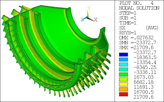
! show cut of all stages and sectors
!------------------------------------
wprot,0,-90,0
/type,1,5
/cplane,1
/shade,1,1
/hbc,1,0
plns,u,sum
plns,s,x
/show,close