This example demonstrates the linear perturbation modal analysis of a simplified multistage system. Specifically, it demonstrates the following key points:
Static analysis of a multistage system when followed by a linear perturbation analysis
Use of base and duplicate sectors for static, HI = 0
Axial multistage modeling
Non-planar interstage boundaries
Modifying stage constraints (harmonic indices)
Expanding and adding to expansion after first expand
The example problem is presented in the following sections:
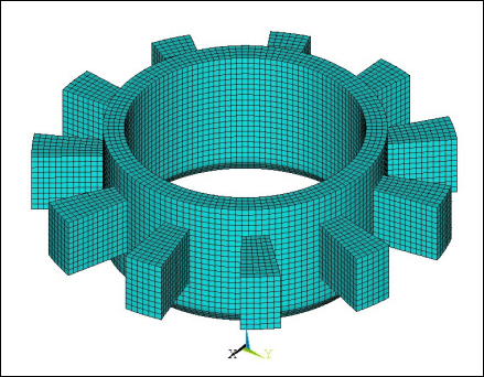
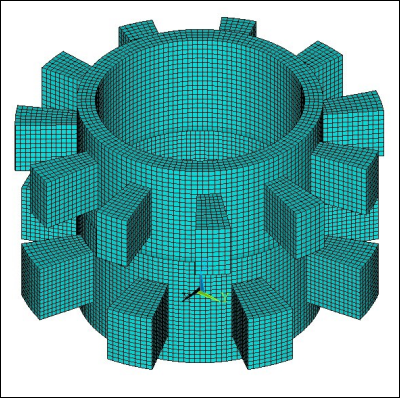
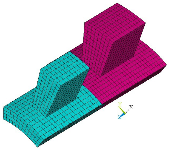
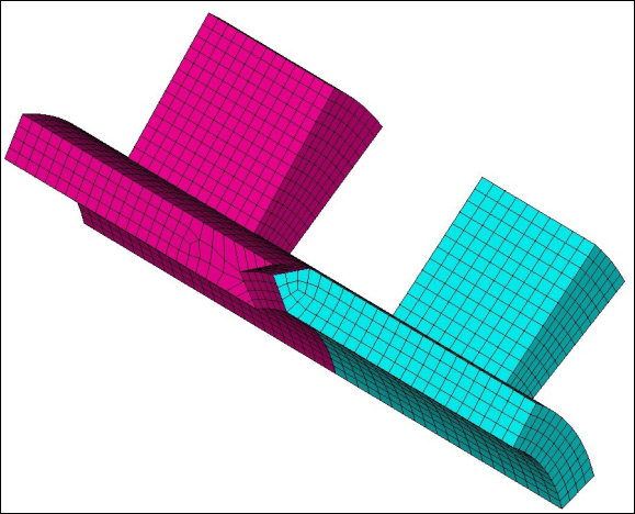
The multistage system consists of two axially aligned cyclic stages merged at a non-planar interstage boundary. Each stage consists of a hub and a blade as shown in Figure 7.6: Multistage Model with Two Axially Oriented Stages. The non-planar interstage boundary with mismatched mesh can be seen in Figure 7.7: Nonplanar Interstage Boundary. Stage 1 has 8 sectors and Stage 2 has 11 sectors. The static analysis is run, and then the linear perturbation modal analysis is run for harmonic index 2.
The following table describes the key steps and related commands used for the example analysis. See Input for the Analysis for the detailed command listing.
| Step | Description | Mechanical APDL Commands |
| 1. | Create base and duplicate sector for each stage. | CDREAD,... |
| 2. | Create stage components for each stage. | CM,... |
| 3. | Create sector low/high edge components for each stage. | CM,... |
| 4. | Create stages and apply cyclic constraints for harmonic index 0. |
MSOPT,NEW,... CECYCMS,... |
| 5. | Set analysis type (static). | ANTYPE,STATIC |
| 6. | Set solution controls. | RESCONTROL,LINEAR |
| 7. | Apply multistage constraints. | CEIMS,... |
| 8. | Apply other boundary conditions. | D,.... |
| 9. | Apply external loading in the form of rotational velocity. | OMEGA,... |
| 10. | Solve the static analysis. | SOLVE,... |
| 11. | Exit solution processor. | FINISH |
| 12. | Re-enter solution processor. | /SOLU |
| 13. | Perform static restart and reform matrices. |
ANTYPE,STATIC,RESTART PERTURB,MODAL SOLVE,ELFORM |
| 14. | Specify modal solve options. |
MODOPT,… MXPAND,… |
| 15. | Modify stages to change harmonic index for modal solve. | MSOPT,MODIFY,… |
| 16. | Recreate interstage boundary constraints without reusing mapping. | CEIMS,,,stag1,stag2 |
| 17. | Solve the modal analysis. | SOLVE |
| 18. | Enter POST1 postprocessor. | /POST1 |
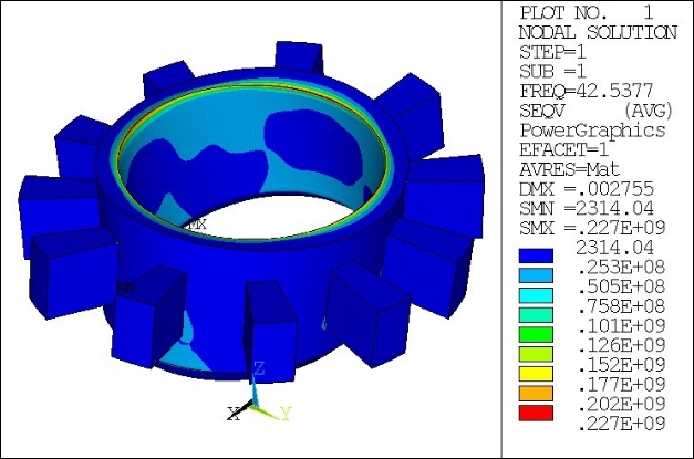
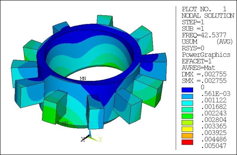
| 19. | Set expansion parameters to expand all sectors of stage 2 only. | MSOPT,EXPA,stag2,ALL |
| 20. | Read results, expand database and expand results. | SET,... |
| 21. | Plot partially expanded displacements. | PLNSOL |
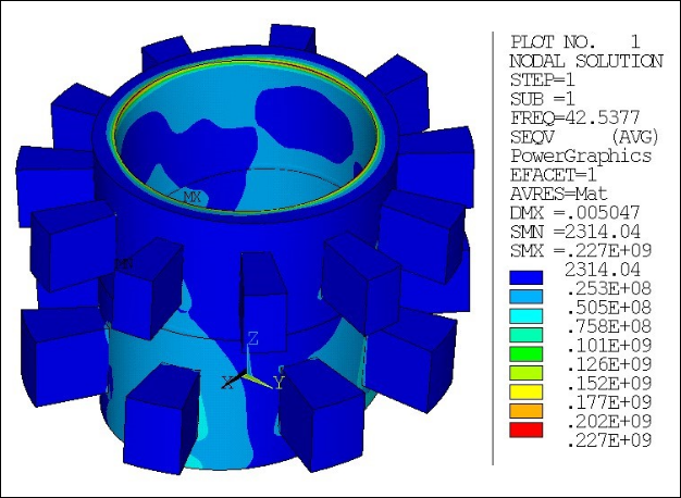
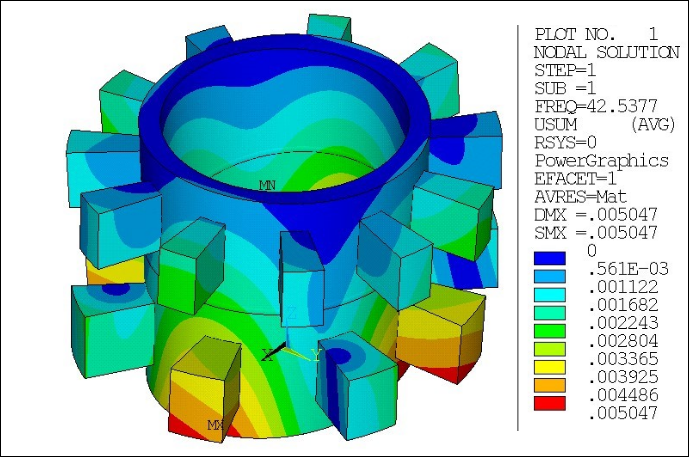
| 22. | Add to multistage expansion. | MSOPT,EXPA,ALL,ALL |
| 23. | Read additional results, expand database and expand results. | SET,... |
| 24. | Plot same expanded displacements | PLNSOL |
Download the zipped .cdb files used for this example problem.
/batch,list
/com ===================================================================
/com        Multistage LP modal analysis - nonplanar MS interface
/com ===================================================================

! input parameters
! ----------------
Nsec_st1 = 8
Nsec_st2 = 11

HI_st1 = 2
HI_st2 = 2

Rint_disk  = 1.7
Rext_disk  = 2

hint_disk  = 2
hmid_disk  = 1.8

/PREP7

! load geometry ! -------------
cdread,db,axial_stage2,cdb       ! stage 2 dupl
*get,max_type_stag2,elem,,typm
cdread,db,axial_stage2,cdb       ! stage 2 base
cdread,db,axial_stage1,cdb       ! stage 1 dupl
*get,max_type_temp,elem,,typm
cdread,db,axial_stage1,cdb       ! stage 1 base

max_type_stag1 = max_type_temp-2*max_type_stag2

! create components for base/duplicate
! --------------------------------
esel,s,type,,1,max_type_stag1
nsle
cm,_stag1_base_nod,node
cm,_stag1_base_elm,elem

esel,s,type,,max_type_stag1+1,2*max_type_stag1
nsle
cm,_stag1_dupl_nod,node
cm,_stag1_dupl_elm,elem

esel,s,type,,2*max_type_stag1+1,2*max_type_stag1+max_type_stag2
nsle
cm,_stag2_base_nod,node
cm,_stag2_base_elm,elem

esel,s,type,,2*max_type_stag1+max_type_stag2+1,2*max_type_stag1+2*max_type_stag2
nsle
cm,_stag2_dupl_nod,node
cm,_stag2_dupl_elm,elem

allsel

! create low and high edges components
! ------------------------------------
csys,1

    ! stage 1 - low edge
    cmsel,s,_stag1_base_nod
    *get,min_y,node,,mnloc,y
    nsel,r,loc,y,min_y
    cm,_stag1_cyclow_nod,node
    *get,nnode_low_stag1,node,,count

    ! stage 1 - high edge
    cmsel,s,_stag1_base_nod
    *get,max_y,node,,mxloc,y
    nsel,r,loc,y,max_y
    cm,_stag1_cychigh_nod,node

    ! stage 2 - low edge
    cmsel,s,_stag2_base_nod
    *get,min_y,node,,mnloc,y
    nsel,r,loc,y,min_y
    cm,_stag2_cyclow_nod,node
    *get,nnode_low_stag2,node,,count

    ! stage 2 - high edge
    cmsel,s,_stag2_base_nod
    *get,max_y,node,,mxloc,y
    nsel,r,loc,y,max_y
    cm,_stag2_cychigh_nod,node

allsel

! create interface components
! ---------------------------
cmsel,s,_stag1_intf_node
cm,intf1_node,node

cmsel,s,_stag2_intf_node
esln
cm,intf1_elem,elem
*get,nnode_intf,node,,count

allsel

FINISH

/com ------> STATIC STEP

/PREP7

! create stages and cyclic constraints: HI = 0 only
! -------------------------------------------------
msopt,new,stag1,Nsec_st1,0
cecycms

msopt,new,stag2,Nsec_st2,0
cecycms

FINISH

/SOLU antype,static
rescontrol,linear,all,1

! interstage coupling
!--------------------
cmsel,s,intf1_node
cmsel,s,intf1_elem
ceims,,,stag1,stag2
! boundary conditions
! -------------------
nsel,s,loc,x,Rint_disk
nsel,r,loc,z,hint_disk+hmid_disk
d,all,all

! loading
omega,,,100

allsel
solve
FINISH

/com ------> LP MODAL STEP
/SOLU
antype,static,restart,,,perturb
perturb,modal
solve,elform

modopt,lanb,6
mxpand,6,,,yes
! Modify stages: change harmonic index
!-------------------------------------
msopt,modify,stag1,HI_st1
cecycms

msopt,modify,stag2,HI_st2
cecycms

! re-create interstage coupling
cmsel,s,intf1_node
cmsel,s,intf1_elem
ceims,,,stag1,stag2
allsel
solve
FINISH

/POST1
file,,rstp

set,list

! Expand all sectors for stage 2
!-------------------------------
msopt,expa,stag2,all
set,1,1

/graphics,power
/vup,,z
/view,,1,1,1
/show,png,rev,,,stage2_eplot
    eplot
/show,close
/show,png,rev,,,stage2_seqv
    plnsol,s,eqv
    *get,max_seqv,plnsol,,max
/show,close
/contour,1,,0,,.005047  !fix contour to similar to both stages
/show,png,rev,,,stage2_usum
    plnsol,u,sum
    *get,max_usum,plnsol,,max
/show,close
/contour

! Add to existing expansion without resetting
! Expand all sector for all stages
msopt,expa,all,all
set,1,1

/graphics,power
/vup,,z
/view,,1,1,1

/show,png,rev,,,ms_eplot
    eplot
/show,close
/show,png,rev,,,ms_seqv
    plnsol,s,eqv
    *get,max_seqv,plnsol,,max
/show,close
/show,png,rev,,,ms_usum
    plnsol,u,sum
    *get,max_usum,plnsol,,max
/show,close

FINISH