The following examples are available:
This example problem demonstrates the calculation of the transient magnetic field in a copper block placed between the pole-pieces of a C-magnet subject to a sinusoidal current excitation. A similar magnetic circuit is described in P.P. Silvester and R.L. Ferrari "Finite Elements for Electrical Engineers" (Third edition), Cambridge University Press (1996), pp. 365-367. In the present example, magnetic circuit parameters have been chosen arbitrarily and the simulation results differ from those in the reference.
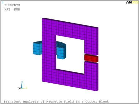
A 2.5 x 5 x 2 cm copper block with electric resistivity ρ = 1.7e-7 Ωm is placed between the pole-pieces of a C-magnet. The magnet consists of a 2.5 cm thick C-shaped iron core with relative permeability μ = 1000 and a 4 cm long cylindrical coil with an average radius of 5 cm carrying a 50 Hz sinusoidal current. The problem considers a half symmetry model of the electromagnet and the block (Figure 8.1: Finite Element Model of the C-Magnet and the Conducting Block) which also includes a 10 cm thick layer of surrounding air.
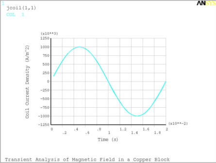
Element SOLID236 is used for all parts of the model. The conducting block is modeled using the electromagnetic analysis option (KEYOPT(1)=1) with time-integrated electric potential (KEYOPT(2)=2). The coil is modeled as a stranded conductor (KEYOPT(1)=0) with a sinusoidal current density (Figure 8.2: Current Density in the Coil) applied as a tabular JS-body load (BFV,,JS,,%jcoil%) with time as a primary variable. The same magnetic analysis option (KEYOPT(1)=0) is used to discretize the iron core (bricks) and the air (tetrahedra).
Flux parallel magnetic boundary conditions (AZ = 0) are imposed on the exterior surfaces of the domain and on the symmetry plane. Zero potential (VOLT = 0) electric boundary conditions are applied on the symmetry plane of the conducting block.
A transient electromagnetic analysis is performed during one full cycle T (T = 0.02 s) to determine the magnetic field in the conducting block. Note that to minimize the size of the output files, only the element results for the element component CCB that includes the coil, core and the block (OUTRES,ESOL,,CCB) are stored.
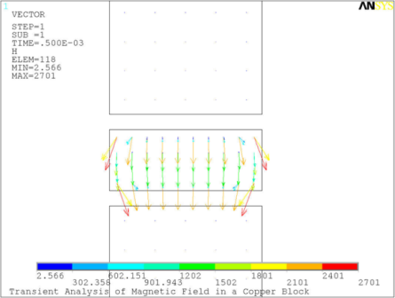
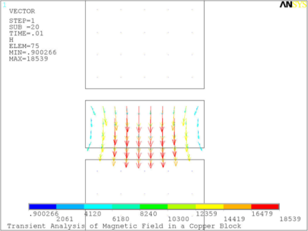
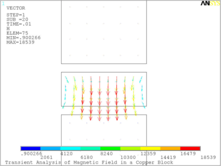
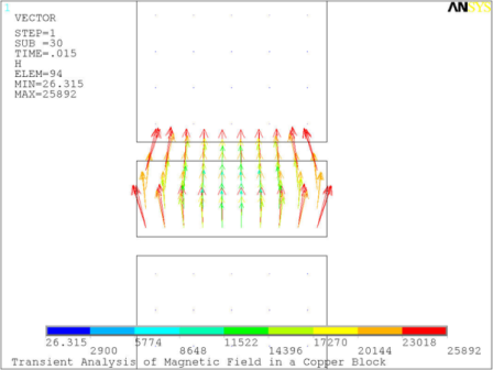
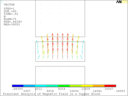
The progression of the magnetic field through the copper block is shown in Figure 8.3: Magnetic Field in the Copper Block at Successive Time Intervals at five successive time intervals T/40, T/4, T/2, 3T/4, and T.
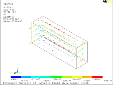
Figure 8.4: Eddy Currents in the Conducting Block shows the eddy currents distribution in the block at the end of the cycle.
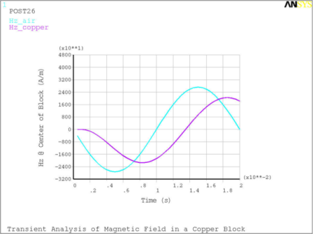
Figure 8.5: Magnetic Field between the Pole-Pieces with and without the Copper Block shows the magnetic field H at the center-point between the pole-pieces in the C-magnet with the copper block in place and without it. The figure demonstrates that the field inside the copper block is attenuated and lagging in phase compared to the external magnetic field.
/title, Transient Analysis of Magnetic Field in a Copper Block
/VUP,1,z
/VIEW,1,3,2,1
/PNU,mat,1
/NUM,1

! *** Problem Parameters
pi=acos(-1)
muo=pi*4e-7

! --- Geometry
a=0.05          ! core and copper block cross section edge length, m
b=0.1           ! distance between inner surfaces of magnetic circuit, m
c=0.02          ! copper block thickness, m
gap=0.005       ! pole face/copper block gap,m

r=0.05          ! coil average radius, m
l=0.04          ! coil length, m
ac=0.025        ! coil cross section edge length, m

dext=0.1        ! extent of domain beyond modeled components, m

esz1=0.005      ! element size of conductive block
esz2=0.01       ! element size of core and coil
esz3=0.05       ! mesh size of surrounding domain

! --- Material properties
muc=1000        ! core relative permeability
mub=1           ! conducting block relative permeability
rho=1.7e-8      ! electric resistivity of copper (Ohm-m)

! --- Excitation parameters
J=1e6           ! coil current density amplitude (A/m^2)
ncyc=1.0        ! number of cycles
nsubT=40        ! number of time steps per cycle
f=50            ! frequency, Hz

! --- Derived parameters
skin=sqrt(rho/(pi*mub*muo*f)) ! skin depth
T=1/f	                        ! time period
tend=ncyc*T                   ! solution time
nsubs=nsubT*ncyc              ! total number of time steps

! table array - sin current vs. time
*dim,jcoil,table,nsubs

*do,i,1,nsubs
 jcoil(i,1)=J*sin(2*pi*f*(i/nsubs)*T)
 jcoil(i,0)=(i/nsubT)*T
*enddo

/axl,x,Time (s)
/axl,y,Coil Current Density (A/m^2)
*vplo,jcoil(1,0),jcoil(1,1)
/com,
/com, *** BLOCK EDGE LENGTH = %a% m, SKIN DEPTH = %skin% m
/com,

/nopr
! *** FE Model
/PREP7
! --- Core
vsel,none
block,0,-a/4, -a/2,a/2, -b/2-5*a/4,b/2+5*a/4
block,0,-a/4, -a/2,2*a+b, -b/2-5*a/4,-b/2-a/4
block,0,-a/4, -a/2,2*a+b, b/2+a/4,b/2+5*a/4
block,0,-a/4, a+b,2*a+b, -b/2-5*a/4,-(gap+c/2)
block,0,-a/4, a+b,2*a+b, gap+c/2,b/2+5*a/4
vovl,all
vatt,2,2,2

! --- Conducting block
vsel,none
block,0,-a/4, a+b,2*a+b, -c/2,c/2
vatt,3,3,3

! --- Coil
vsel,none
cyli,r-ac/2,r+ac/2, -l/2,l/2, 90,180
cyli,r-ac/2,r+ac/2, -l/2,l/2, 180,270
allsel,belo,volu
numm,kp
vatt,4,4,4,14
allsel

cm,keep_v,volu

! --- Air box
*get,xmin,kp,,mnloc,x
*get,ymin,kp,,mnloc,y
*get,ymax,kp,,mxloc,y
*get,zmin,kp,,mnloc,z
*get,zmax,kp,,mxloc,z
vsel,none
block,xmin-dext,0, ymin-dext,ymax+dext, zmin-dext,zmax+dext
cm,scrap_v,volu
allsel
vsbv,scrap_v,keep_v,,dele,keep
cmse,u,keep_v
cm,air_v,volu
vatt,1,1,1
allsel

! --- Air
et,1,236            ! AZ
mp,murx,1,1

! --- Core
et,2,236            ! AZ
mp,murx,2,muc

! --- Conducting block
et,3,236,1,2        ! AZ + time-integrated VOLT
mp,murx,3,mub
mp,rsvx,3,rho

! --- Coil
et,4,236            ! AZ
mp,murx,4,1

cswp,14,1	        ! cylindrical ESYS for coil current direction
csys

vsel,s,mat,,3       ! brick mesh for the block
esize,esz1
vmesh,all

vsel,s,mat,,2,4,2   ! brick mesh for the coil and core
esize,esz2
vmesh,all

vsel,s,mat,,1       ! mesh air box (hex-to-tet)
esize,esz3
mshape,1
vmes,all
allsel
eplo

! Define Coil-Core-Block element component
esel,s,type,,2,4
cm,CCB,elem
eplo
allsel

! *** Boundary Conditions and Loads
asel,s,ext
da,all,az           ! flux parallel magnetic BCs

vsel,s,mat,,3
allsel,belo,volu
asel,r,loc,x
da,all,volt         ! current normal to symmetry plane

vsel,s,mat,,4
bfv,all,js,0,%jcoil%,0  ! tabular current density load
allsel
fini

! *** SOLVE
/SOLU
antype,trans
time,tend
nsub,nsubs
outres,esol,all,CCB
kbc,1     ! step applied load
solve
fini

! *** POST PROCESS
/POST1
!set,,,,,0             ! results at time=0 s
!set,,,,,T/4           ! results at time=T/4 s
!set,,,,,T/2           ! results at time=T/2 s
!set,,,,,3*T/4         ! results at time=3*T/4 s
set,last,last
cmsel,s,CCB            ! select coil, core and conducting block
plve,h,,,,vect,,on     ! plot magnetic field
esel,s,mat,,3          ! select conducting block
plve,jt,,,,vect,,on    ! plot current density
allsel
fini

*dim,Hz,array,nsubs
/post26
ansol,2,node(0,3*a/2+b,0),h,z,Hz_copper
/axl,x,Time (s)
/axl,y,Hz @ Center of Block (A/m)
plva,2
vget,Hz,2
fini

/PREP7
et,3,236  ! replace copper block by an 'air' block
fini

! *** Repeat solution
/SOLU
antype,trans
time,tend
nsub,nsubs
outres,esol,all,CCB
kbc,1     ! step applied load
solve
fini

/POST26
ansol,2,node(0,3*a/2+b,0),h,z,Hz_air
/axl,x,Time (s)
/axl,y,Hz @ Center of Block (A/m)
vput,Hz,3,,,Hz_copper
plvar,2,3
fini
Another Ansys, Inc. publication, the Mechanical APDL Verification Manual, contains other examples of various types of analyses, including the following 3D transient edge-based magnetic analysis example:
VM121 -- Voltage Forced Coil (1/8 Symmetry)


