VM121
VM121
Voltage Forced Coil
Test Case
A circular coil of rectangular cross-section is modeled between two aluminum plates (first solution) and in free-space (second solution). A transient analysis is performed with a 20 volt step excitation. The total current flowing through the coil is calculated.
| Material Properties | Geometric Properties | Loading |
|
µr = 1.0 (Air) µr = 1.0 (Plate) µr = 1.0 (Coil) R = 12.4 Ω (Resistance of Coil) R = 3 x 10⁻⁸ Ω-m (Resistivity of Plate) |
Coil: n = 700 turns Ri = 0.087 m (Inner Radius) H = 0.028 m (Height) Ro = 0.116 m (Outer Radius) Plates: 0.24 x 0.24 x 0.0127 m3 Gap = 0.03435 m |
V = 20 Volt |
Analysis Assumptions and Modeling Notes
This model solves the voltage forced coil problem using 20-node electromagnetic SOLID236 elements with different key options:
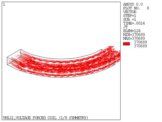
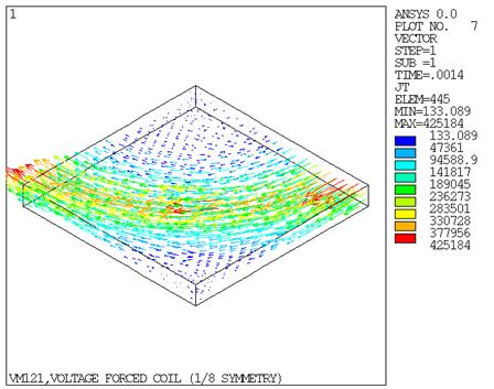
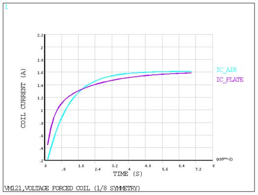
A 1/8 symmetric 3D model is constructed (Figure 171: Finite Element Mesh of the Coil and Plate). The step voltage input is applied on the coil. The current source density in the coil and the plate are shown in Figure 173: Current Density in the Plate and Figure 174: Coil Current vs. Time .
The target data is obtained from Figure 4 in the reference paper.
Results Comparison
| Time=1x10⁻² sec | Target | Mechanical APDL | Ratio |
| Current in coil with plate (A) | 1.160 | 1.156 | 0.997 |
| Current in coil in free space (A) | 0.970 | 0.975 | 1.005 |
| Time=4x10⁻² sec | Target | Mechanical APDL | Ratio |
| Current in coil with plate (A) | 1.510 | 1.512 | 1.002 |
| Current in coil in free space (A) | 1.570 | 1.578 | 1.005 |
| Time=7x10⁻² sec | Target | Mechanical APDL | Ratio |
| Current in coil with plate (A) | 1.580 | 1.586 | 1.004 |
| Current in coil in free space (A) | 1.610 | 1.611 | 1.000 |


