For cyclically symmetric loading, support is available for linear static and large-deflection nonlinear static solution options. Cyclically symmetric loading implies any load applied on the cyclic sector representing a loading pattern that is repetitive at sector angle increments around the 360° structure.
When contact elements are present in a large-deflection nonlinear static analysis, a quasi-static transient solution (ANTYPE,TRANSIENT with TINTP,QUAS) can be used to overcome convergence issues. For more information, see Transient Dynamic Analysis Options in the Structural Analysis Guide. Note that all other transient analyses are not supported.
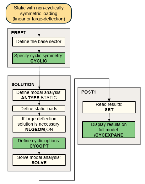
The following flowchart illustrates the process involved in a static (linear or large-deflection) cyclic symmetry analysis with cyclically symmetric loading.
Only a harmonic index zero solution is valid for a static solution with cyclically symmetric loading.
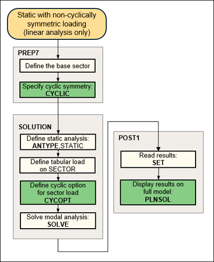
For non-cyclically symmetric loading, the program supports linear static analysis only. The following flowchart illustrates the process involved in a static cyclic analysis with non-cyclically symmetric loading.
Non-cyclically symmetric loading cannot be applied when thermal loading is present.
For more information, see Non-Cyclically Symmetric Loading.
An initial state can be defined in a static cyclic symmetry analysis using the
INISTATE command. Only stress and strain initial states are
supported for cyclic symmetry models. In order to comply with cyclic symmetry, you
must set the initial state coordinate system to the cyclic coordinate system using
the command INISTATE,SET,CSYS,Val2.
Failure to set the coordinate system will result in a non-cyclic application of the
initial state, and results will be non-cyclic.
Example 4.2: Applying an Initial State in a Cyclic Symmetry Analysis
/com, -------------------------------------------
/com, Create cyclic model
/com, -------------------------------------------
/prep7
et,1,182
mp,ex,1,1e7
mp,nuxy,1,.3
mp,dens,1,1.0
local,11,1      ! Cyclic coordinate system is 11
n,1,1
n,2,2
n,3,2,90
n,4,1,90
e,1,2,3,4
nrotate,all
nsel,,loc,x,1
d,all,uy
allsel
cyclic
finish

/com, --------------------------------------------
/com,  Cyclic static solve with initial state
/com, --------------------------------------------
/solu
antype,static
inistate,set,dtyp,epel  ! Use strain data for initial state definition
inistate,set,csys,11    ! Ensure initial state is applied in the cyclic coordinate system
inistate,define,,,,,0.05,  ! Initial state strain value (Cxx) is 0.05
solve
finish
If cyclic expansion via the /CYCEXPAND command is active, the PLNSOL and PRNSOL commands have summation of all required harmonic index solutions by default.
In a static analysis with non-cyclically symmetric loading, all applicable harmonic index solutions are computed and saved in the results file as load step results.
A SET,LIST command lists the range of load step numbers in the group containing each solution. Each load step post data header contains the first, last, and count of load steps from the given SOLVE command, as shown:
        *****  INDEX OF DATA SETS ON RESULTS FILE  *****
SET  TIME/FREQ  LOAD STEP  SUBSTEP  CUMULATIVE  HRM-INDEX  GROUP
1    1.0000     1          1        1           0          1-3
2    2.0000     2          1        2           1          1-3
3    3.0000     3          1        3           2          1-3
4    1.0000     1          1        1           0          4-6
5    2.0000     2          1        2           1          4-6
6    3.0000     3          1        3           2          4-6
...
The SET command establishes which SOLVE load step group should display. Summation via /CYCEXPAND is automatic. Plots and printed output show the summation status.
With /CYCEXPAND turned on, the results are expanded at each
load step and then combined to plot the full solution as a complete sum. For
example, in a four sector model where the harmonic index results 0 through 2 are
available in the results file, the plot command PLNSOL will
display the results as STEP=1 THRU=3 COMPLETE
SUM.
Accumulation occurs at the first applicable PLNSOL or PRNSOL command. After accumulation, the last load step number of the current group becomes the new current load step number.


