In this example, you will perform an electromechanical-circuit analysis of a MEMS structure.
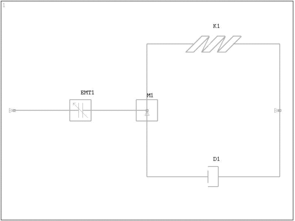
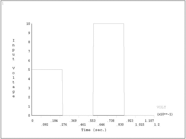
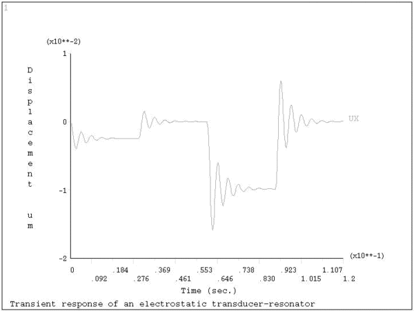
This is an analysis of a micro-mechanical system composed of an electrostatic transducer coupled to a mechanical resonator as shown in Figure 5.4: Electrostatic Transducer - Resonator Model. A discrete spring, mass, and damper represent the mechanical resonator. A discrete electromechanical transducer represents the parallel plate capacitor. The electrostatic transducer has a series of pulse excitation voltages applied as shown in Figure 5.5: Excitation Voltages. Our goal is to compute the time-transient displacement of the mechanical resonator (at Node 2).
The problem can be easily built in the Circuit Simulator using the electromechanical transducer element (TRANS126), the mass element (MASS21), and the combination element (COMBIN14). The problem uses the µMKSV system of units. For a parallel plate capacitor, the capacitance varies as a function of the gap. The real constant C0 represents the capacitance relationship.
Four load steps simulate two pulse excitations on the transducer. You can apply the voltage to the transducer either directly at the node (D), or through the use of the general circuit element (CIRCU124). A large-signal nonlinear transient solution is run using auto time-stepping (AUTOTS). The resulting displacements are plotted using POST26.
The following are the input parameters:
| Plate area = 1 x 10⁸ ( µm)2 |
| Initial gap = 150 µm |
| Relative permittivity = 1.0 |
| Mass = 1 x 10⁻⁴ Kg |
| Spring Constant = 200 µN/ µm |
| Damping Coefficient = 40 x 10-3 µNs/ µm |
The excitation at node 2 is:
| Time (sec) | Value (Volts) |
|---|---|
| 0.00 | 5.0 |
| 0.03 | 0.0 |
| 0.06 | 10.0 |
| 0.09 | 0.0 |
| 0.12 | 0.0 |
Figure 5.6: Mechanical Resonator Displacement (at Node 2) shows the resulting displacement.
The command listing below demonstrates the problem input (captured and edited from the Circuit Builder). Text prefaced by an exclamation point (!) is a comment.
/batch,list
/show,file
/prep7
/title, Transient response of an electrostatic transducer-resonator
/com,    µMKSV units

et,1,trans126          ! EM Transducer Element
r,1,,1,150             ! gap=150  µN
rmore,8.854e-6*1e8     ! C0 term (eps*area)
n,1
n,2,0.1
e,1,2

et,2,21,,,4            ! Mass element (UX,UY dof option)
r,2,1e-4               ! Mass
rmod,2,7,,1
type,2
real,2
e,2

et,3,14,,1             ! Spring
keyopt,3,7,1           ! This is an undocumented keyopt used to suppress
                       ! a warning message about noncoincident nodes.
                       ! It does not alter the performance of the element.
                       ! It is not intended for general use.
r,3,200,,,.05,1        ! k=200  µN/ µm, graphical offsets
n,3,0.2
type,3
real,3
e,2,3

et,4,14,,1             ! Damper
keyopt,4,7,1           ! This is an undocumented keyopt used to suppress
                       ! a warning message about noncoincident nodes.
                       ! It does not alter the performance of the element.
                       ! It is not intended for general use.
r,4,,40e-3,,-.05,1     ! Damping coeff=40e-3  µMs/ µm, graphical offsets
type,4
real,4
e,2,3

nsel,s,node,,1,3,2
d,all,ux,0             ! Fix transducer and ground
nsel,all
d,1,volt,0             ! Fix voltage ground
d,2,uy,0               ! Fix UY motion for mass
finish

/solu
antyp,trans            ! Transient analysis - large signal
kbc,1                  ! Step boundary conditions
d,2,volt,5             ! Apply 5 volts to transducer
time,.03               ! Time at end of first load step
deltim,.0005,.0001,.01 ! Set initial, minimum and maximum time incr.
autos,on               ! Use auto time-stepping
outres,all,all         ! Save all intermediate time point results
cnvtol,f               ! Convergence on force
solve                  ! Solve
time,.06               ! Repeat for addition load steps
d,2,volt,0
solve
time,.09
d,2,volt,10
solve
time,.12
d,2,volt,0
solve
finish
/post26
nsol,2,2,u,x           ! Retrieve displacement
/xrange,0,.12
/yrange,-.02,.01
/axlab,x,Time (sec.)
/axlab,y,Displacement (micro meters)
plvar,2                ! Plot displacement
finish


