This example problem uses the FLUID220 element to demonstrate acoustic propagation in a lined guide with the complex impedance boundary and mean flow.
The lined duct with the dimension 4x1x0.075 m3 is terminated by Perfectly matched layers (PML) in the acoustic propagating direction.
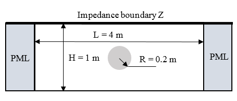
The impedance boundary with the complex impedance Z = 417.45+j417.45 ohms is applied on the top boundary of the duct. The bottom boundary is set to the rigid wall.
The volume mass source is located at the center of the duct to model a monopole source with radius = 0.2 m. The nodal mass source is set to q=1/ω (ω is the angular frequency).
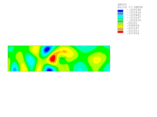
The uniform mean flow with Mach number = 0.3 in the x-direction is investigated. The working frequency is 384.36 Hz.
The acoustic domain is the air with mass density = 1.21 kg/m3 and sound speed = 345 m/s. It is necessary to use PML to truncate the duct, rather than the matched impedance boundary, since multiple modes may be excited in the model.
/batch,list
/nopr
/prep7
pi=acos(-1.)
c0=345                       ! sound speed in the air
rho=1.21                     ! the air mass density
mach=0.3                     ! Mach number
v0=mach*c0                   ! mean flow velocity
k=7                          ! working wave number
freq=k*345/(2*pi)            ! working frequency
wavelen=c0/freq              ! wave length
h=wavelen/12                 ! mesh size
d=2                          ! half length of duct
w=0.5                        ! half height of duct
c=0.075                      ! thickness of duct
dpml=0.5*wavelen             ! thickness of PML
r=0.2                        ! radius of monopole
z0=c0*rho                    ! wave impedance in the air
omega=2.*pi*freq             ! angular frequency
q=1./omega                   ! mass source
x0=-r*cos(pi/4.)
y0=r*sin(pi/4)
et,1,220,,1                  ! acoustic element
et,2,220,,1,,1               ! acoustic PML element
mp,dens,1,rho                ! air mass density
mp,sonc,1,c0                 ! sound speed in the air
! generate geometry
k,1,0,0,0
k,2,0,r,0
k,3,0,w,0
k,4,-d,w,0
k,5,-d,0,0
k,6,-r,0,0
k,7,x0,y0,0
k,8,-d-dpml,0
k,9,-d-dpml,w
l,1,2
l,2,3
l,3,4
l,4,5
l,5,6
l,6,1
larc,2,7,1,r
larc,7,6,1,r
l,4,7
l,4,9
l,5,8
l,8,9
al,7,2,3,9
al,1,7,8,6
al,4,5,8,9
al,4,10,12,11
aglue,all
! generate mesh
et,11,200,7
type,11
esize,h
amesh,all
asel,all
asel,u,,,4
esize,,1
type,1
mat,1
vext,all,,,0,0,c
asel,s,,,4
type,2
mat,1
esize,,1
vext,all,,,0,0,c
asel,s,loc,z,0
aclear,all
etdele,11
vsymm,x,all
vsymm,y,all
nummrg,all
alls
nsel,s,loc,x,-d-dpml
nsel,a,loc,x,d+dpml
d,all,pres,0                 ! zero velocity potential on PML exterior
nsel,s,loc,y,w
sf,all,impd,z0,z0            ! impedance boundary on the top
alls
csys,1
nsel,s,loc,x,0,r
bf,all,mass,q,90             ! mass source
alls
csys,0
nsel,all
bf,all,vmen,v0,0,0,          ! uniform mean flow in x-direction
alls
fini
/solu                        ! solution
eqslv,sparse
antype,harmic
harfrq,freq
nsub,1
solve
fini
/show,png
/post1
set,1,1
plns,pres                    ! nodal pressure
fini
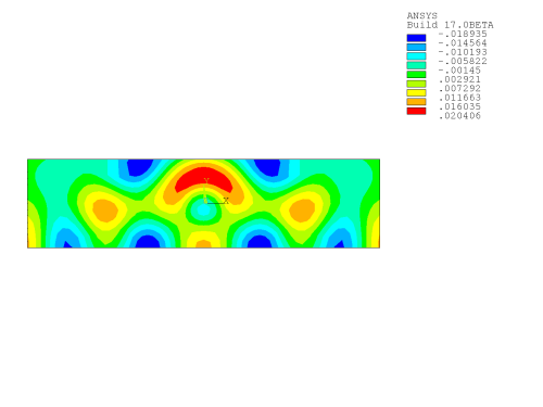
The acoustic pressures without and with mean flow are shown in the figures below.