In addition to simulating the additive build process, you can simulate removal of the part and/or supports by checking the Displacement After Cutoff output option. Cutoff Mode determines what will be cut off whereas Cutoff Method determines how it will be cut off. The various option combinations are illustrated at the end of this section.
Simulation results will include a voxelized representation of the part with predicted displacements after the cutoff occurs.
Cutoff Mode
Use the Cutoff Mode drop-down to select what elements of the model will be removed:
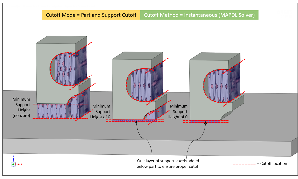
Part and Support Cutoff - The part and supports are cut from the baseplate and cut from each other at the part-support boundaries. If the part touches the baseplate, one layer of support voxels is added below the part to avoid cutting the part.
In the case where you have chosen to simulate without supports (that is, you have unchecked Simulate with Supports in the Supports section of the simulation form) and you choose Displacement After Cutoff/Part and Support Cutoff, one layer of support voxels will be added to the base of the part to simulate part after cutoff so as to avoid cutting the part. (See Simulating Without Supports.)
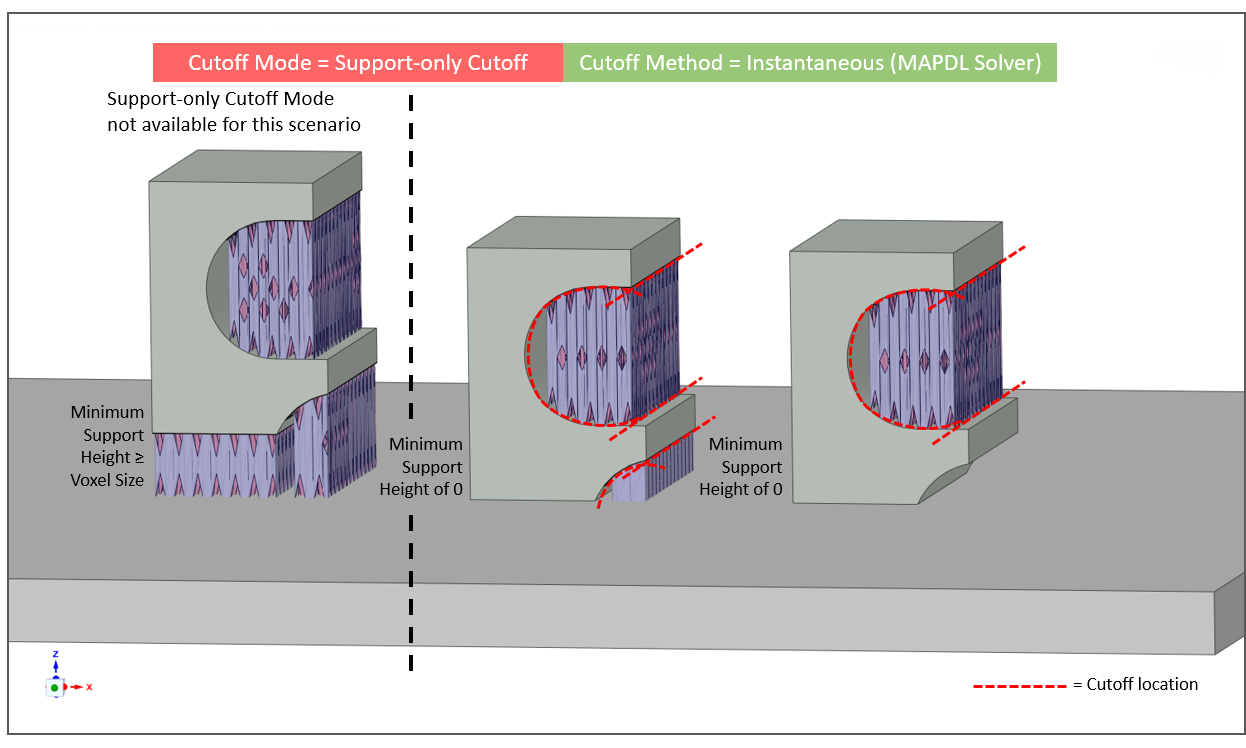
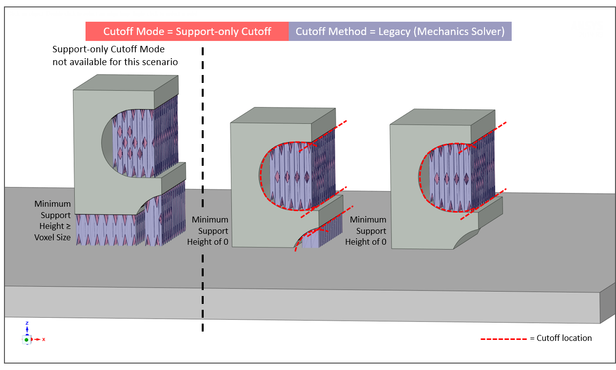
Support-only Cutoff - The support voxels are cut at the part-support boundaries, separating the part from the support, but not the part from the baseplate. This option is available only if the Minimum Support Height is less than the Voxel Size, otherwise it is disabled. This ensures that there are part voxels touching the baseplate, thereby keeping the part attached to the baseplate even after support removal.
Cutoff Method
Use the Cutoff Method drop-down to select how the cutoff will occur:
Instantaneous (default) - This method uses the Mechanical APDL solver to simulate instantaneous cutoff of part and support, or support-only, depending on the Cutoff Mode.
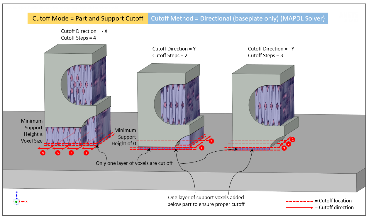
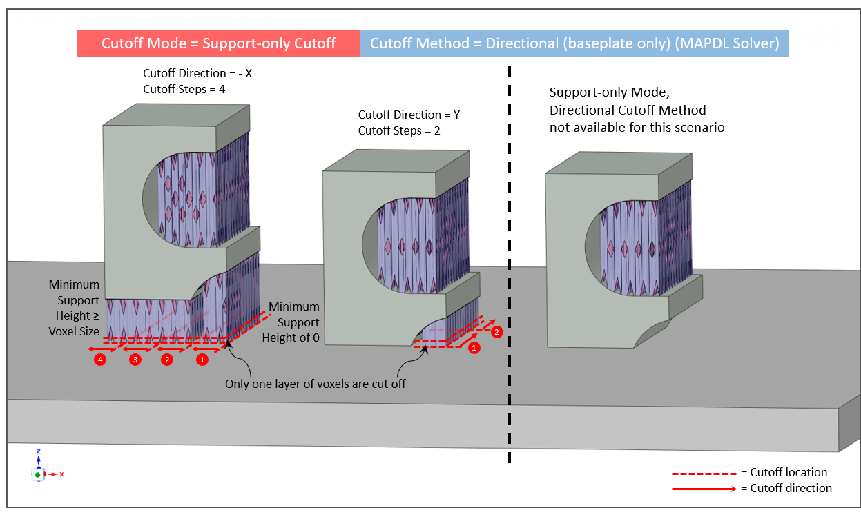
Directional (baseplate only) - This method uses the Mechanical APDL solver to simulate a progressive cutoff at the baseplate, that is, at the bottom layer of elements only, in which you specify the number of step increments and the direction for removal from the baseplate.
Cutoff Direction - The direction in which the support and/or part will be progressively removed. Choose either the +X, -X, +Y, or -Y direction. Refer to the triad legend for directional perspective.
Cutoff Steps - The number of incremental steps taken to complete the directional cutoff.
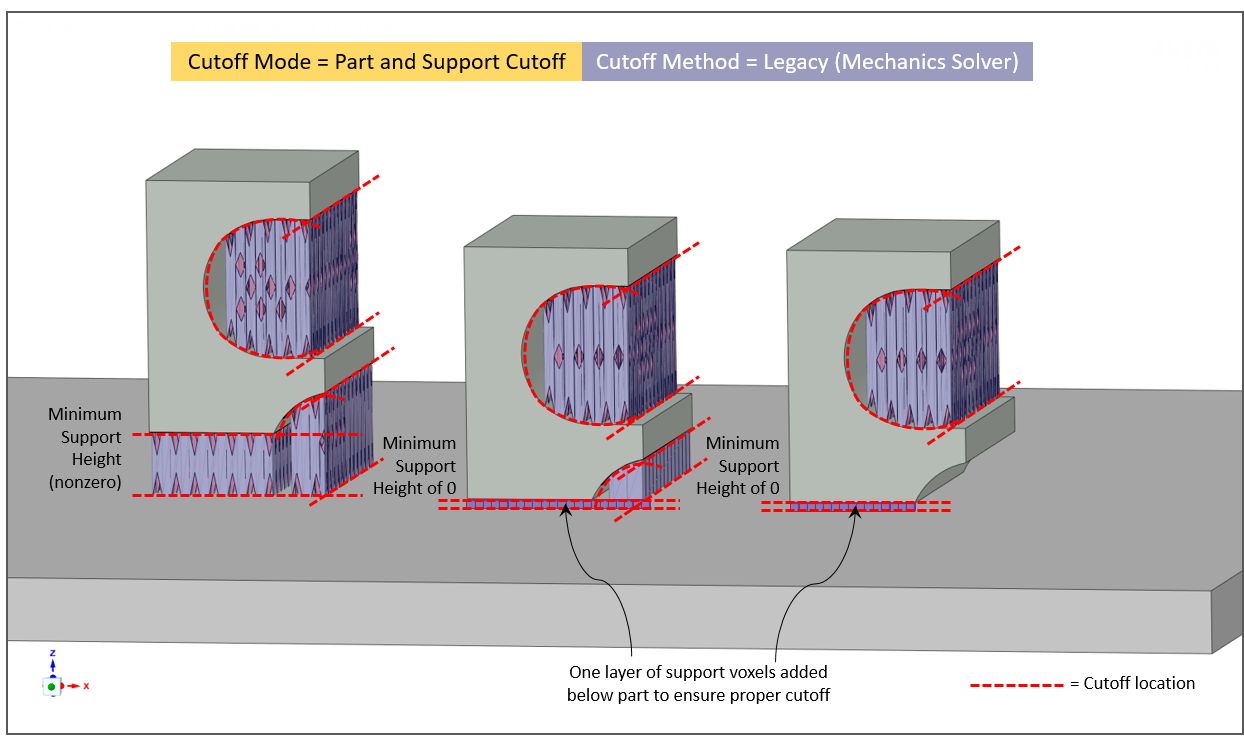
Legacy - This method is visible only if you have Legacy Options = Show under Settings in the menu bar. Legacy uses the Mechanics solver to simulate cutoff scenarios rather than the default Mechanical APDL solver.
Note that if you Restart an old simulation that used the Mechanics solver for cutoff (releases prior to 2020 R2), the Legacy option will be set automatically and the Mechanics solver will be used. Use the Duplicate button on the original completed simulation to bring up the simulation form if you want to change cutoff options.
Illustrations of the various option combinations are provided here.