


The Additive Prep Machine Options form is shown below. This is the same form that you will find under Settings > Manage Machines. After making changes on the form, be sure to scroll to the bottom to click Save Changes. Use the Discard Changes button to clear the form whenever needed.
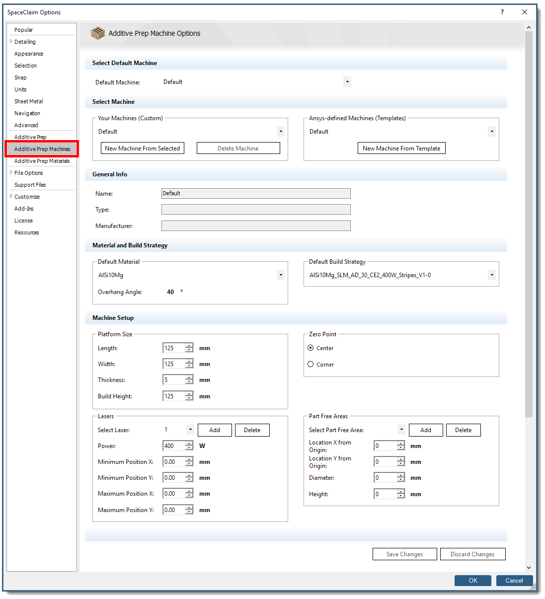
Select Default Machine
Select a machine from the drop-down list to be the default machine upon application startup.
Select Machine
To add or edit machines into your customized machine user profile, start with one of your existing custom machines, or from an Ansys-defined machine, as a starting point.
Click New Machine from Selected to create a new machine from the machine currently selected in the drop-down under Your Machines (Custom).
Click Delete Machine to delete the machine currently selected in the drop-down under Your Machines (Custom) from your machine user profile.
Click New Machine from Template to create a new machine using one of the predefined templates available under the drop-down Ansys-defined Machines (Templates).
After any of the above actions, make your changes to the options on the form, as appropriate. Scroll down to the bottom of the page and click Save Changes.
General Info
Whether it's Susi, Big Red, or Left Corner, give your machine a unique Name to easily distinguish it. Type and Manufacturer are read-only information fields, read from your selected machine.
Material and Build Strategy
Select the default material to be used at application startup.
Note: The machine material assigned here will override any material that may be assigned in SpaceClaim properties (right-click an object, Properties > Material).
Select the default build strategy to be used at application startup.
Machine Setup
Platform Size
These settings control the size of the Build Volume as shown here.
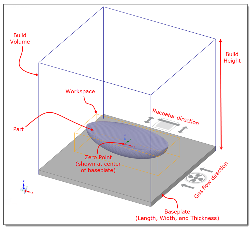
Length: Dimension of the baseplate in the X direction, in millimeters.
Width: Dimension of the baseplate in the Y direction, in millimeters.
Thickness: Thickness of the baseplate (Z direction), in millimeters. The thickness is included in the Build Height.
Build Height: Height of the Build Volume, in millimeters. This is typically the height that the build chamber allows on your machine.
When you create a new machine from a template, the size parameters automatically populate for the new machine.
Zero Point: Location of the origin on the top surface of the baseplate. Options include placing the origin at the center or at the corner of the baseplate.
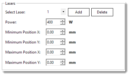
Lasers
Here you can identify multiple lasers.
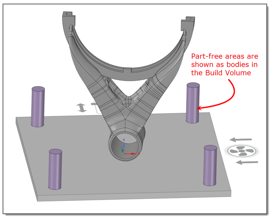
Here you can identify areas on the baseplate designated as no-scan regions, such as locations of bolt holes. If there are four corner bolt holes, add four separate part-free areas. Part-free areas are defined as cylindrical bodies. Their centers should be located relative to the zero point of the Build Volume.
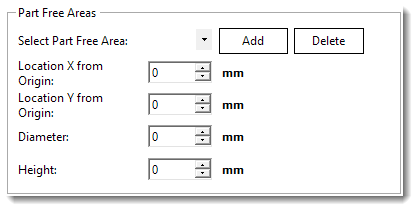
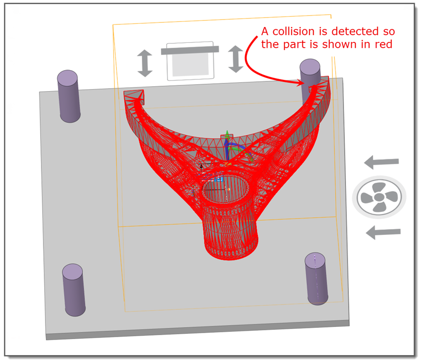
You will be prevented from moving or orienting parts into a part-free area. Your part will appear red indicating a collision with part-free areas. Collision detection is performed on design bodies (.scdoc) only, not on faceted bodies (.stl), which includes supports.