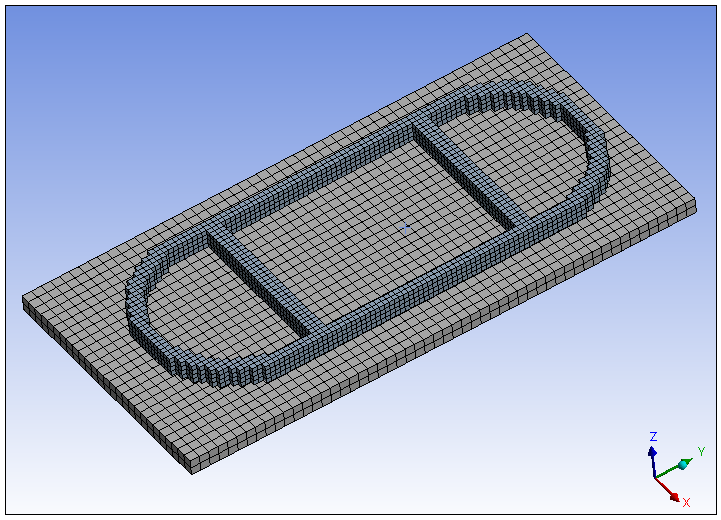
For the part, we recommend one finite element layer per real deposition layer. A DED process simulation does not need a strictly layered mesh with identical layer height for every layer as does a Powder Bed Fusion simulation, but the DED weld track must be represented in the mesh.
A slightly coarser mesh is acceptable for the base plate because it is simply serving as a heat sink and a fixed support in the simulation.
Mesh types to consider include Cartesian, tetrahedrons, and sweep mesh. We recommend a hex mesh (i.e., Cartesian) rather than a tetrahedrons mesh if you will be using manual clustering because, for some geometries, some tetrahedrons may be excluded from element clusters. We also recommend using linear elements rather than quadratic.
Procedural Steps
The following steps describe the Cartesian mesh technique:
Set mesh controls for the part. The size of the mesh is required to be the same throughout all part bodies.
Right-click Mesh and select Insert > Method. An Automatic Method object appears under the Mesh object.
Select the part body. In the details pane of the Automatic Method object, click Apply next to Geometry.
Select the dropdown in the Method option and choose Cartesian. Notice the Automatic Method object has been renamed to Body Fitted Cartesian.
In the details pane of the Body Fitted Cartesian object, under Definition, set the Element Size to the desired value. (Click in the right column on the word Default to activate the text field.)
Under Advanced, set the Projection Factor to a value between 0 and 1. The Projection Factor defines how well the mesh fits to the geometry. A value of 0 results in cubic elements with a rough fit to the geometry. Increasing the Projection Factor changes the shape of the elements to better fit the geometry and may yield better results in some cases, but may also result in an overlapping or failed mesh. Our recommendation is to use 0, or close to 0, initially and then iterate from there to see the effects of changing Projection Factor.
Too large of a Projection Factor may result in:
Highly distorted mesh resulting in cluster layers that are unacceptably uneven: While a small amount of irregularity in the mesh layers is acceptable, if you increase the Projection Factor too much, at some point element clustering is adversely affected, or clusters may even be impossible to generate.
Overlapping mesh at the contact region: An overlapping mesh between the part and the base is not desirable. The required contact connection may still be generated but during the solution, the heat does not get properly conducted to the base because of the small negative gap.
You can apply a Coordinate System for the mesh. Typically, the default global coordinate system is appropriate but you may want to set it to one located on the top surface of the base plate.
For additional information about Cartesian meshes, see Cartesian Method Control in the Meshing User's Guide.
Set mesh controls for the base plate. Highlight the Mesh object and right-click Insert > Sizing. A Sizing object is created under the Mesh object and becomes active.
Select the base plate body and hit Apply in the Details view.
Under Definition, change the Element Size to the desired value. It can be larger than the element size for the part.
Click the Mesh object and, in Details, change the Element Order to Linear. This will set a global control for all bodies to be meshed.
Finally, highlight the Mesh object and right-click Generate Mesh. If you don't like the generated mesh you can easily go back and change element sizes, then right-click Mesh and select Update.


