


Connections are the mechanism to ensure that the part and the base plate bodies in the simulation are aware of each other and can share data (temperatures and displacements) across boundaries. The connection type that is typically used in DED process simulations is a special case of bonded contact between the element faces on the bottom of the build and the element faces on the top of the base. The name of this contact must be DED_Contact. (The DED_Contact name is automatically assigned when using the DED Process Wizard.)
Procedural Steps
In the project tree, a Contacts object is automatically added under Connections with a Contact Region object underneath it when using the DED add-on. The Contact Side is defined as the lower element faces of the print part. The Target Side is defined as the upper element faces of the base plate.
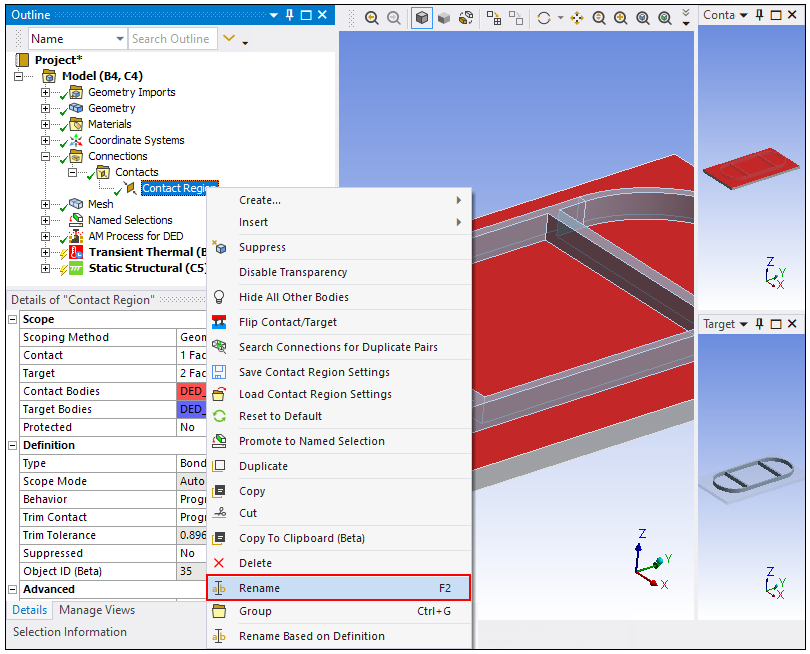
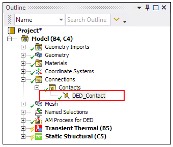
Expand the Contacts object and right-click Contact Region. Choose Rename and enter DED_Contact as the new name. This is required for solution of the DED simulation.
The recommended settings (by default since release 2023 R1) for the DED_Contact can be seen below; the Contact surface is the lower element faces of the print part and the Target surface is the upper element faces of the base plate. The Behavior is recommended to be Asymmetric with Nodal-Normal from Contact as the Detection Method. This setting is seen to be helpful to eliminate or reduce the negative temperature issue due to thermal shock found in previous releases. Defining contact between build and base can be challenging sometimes. Recommended settings may not work for your case. For more information, refer to the Contact Technology Guide.
