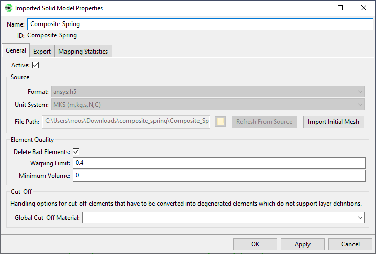
An Imported Solid Model object is automatically generated in ACP (Pre) as soon as a Mechanical model is linked to an ACP Setup component. The file format, unit system, and file path are automatically set and cannot be changed.
The Imported Solid Model object also contains the Named Selections which were generated in the upstream component. They appear as Mesh Components as shown below. You can see the mesh of the Imported Solid Model (even before you define any settings for the mapping) by right-clicking Composite_Spring and selecting Import Initial Mesh from the context menu.
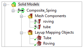
In this example, the lay-up mapping is split into two pieces, one for the Tube and one for the Roving. So, a Lay-up Mapping Object is generated for each of these regions
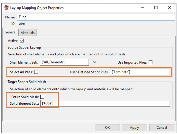
The source plies for the region Tube are the woven and core plies which are all defined in the Modeling Group Laminate. The configuration of the Lay-Up Mapping Object is shown below.
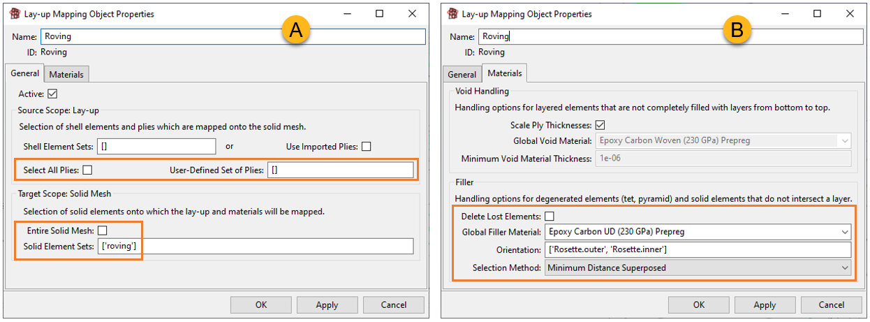
The filler option is used to assign the UD material to the roving mesh component. The filler option is activated by passing an empty list of plies and defining a filler material and orientation. In the figure below, the filler options for the roving are shown– the General options (A) and the Materials options (B).
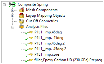
The mapped plies and generated materials are displayed under the Analysis Plies folder of the Imported Solid Model. You can use these entities to plot ply-wise data such as thickness and fiber directions.
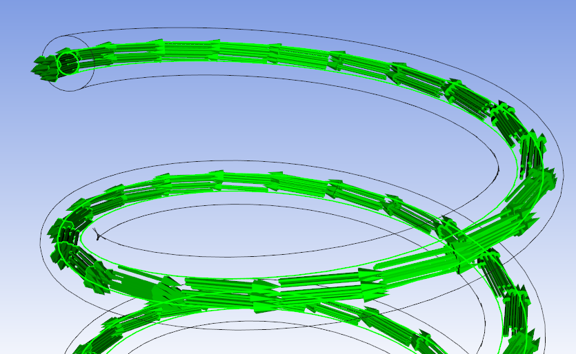
The figures below show the final solid mesh with mapped plies and UD materials. The first figure shows the first ply on the solid mesh, its thickness and material orientations.
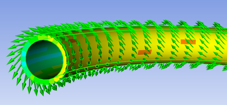
The assignment of the UD material is shown in the next figure. It shows that the orthotropic material (UD carbon) is perfectly aligned with the extrusion direction of the spring thanks to the selected Rosettes and Selection Method.