


This section guides you through modeling the kiteboard with three Modeling Plies in ACP (Pre):
In earlier tutorials, you learned the importance of Rosettes and Oriented Selection Sets (OSS) in composite modeling. In this section, you will create a Rosette and an OSS.
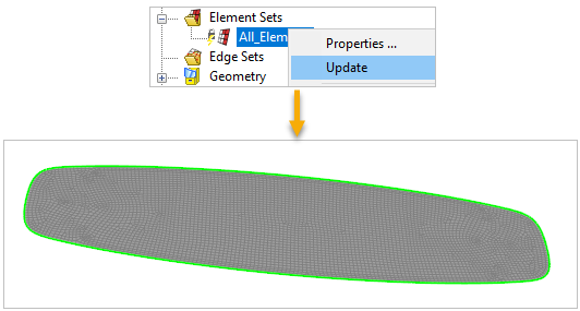
In the Tree View, expand Element Sets. Right-click All_Elements and select Update. The Element Set is visible in your model.
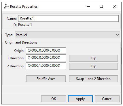
Create a Rosette by following the instructions in Defining the Rosette and using the specifications as shown in the image below.
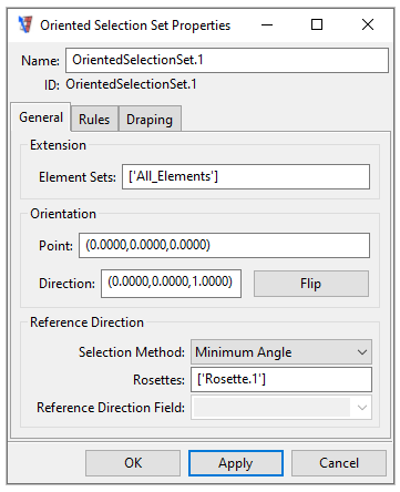
Create an OSS by following the steps in Defining the Base Plate's Oriented Selection Set and using the property values as shown in the image below.
In this section, you will create the kiteboard's bottom Modeling Ply using the stackup and configure a section cut to verify the correct layering of the ply.
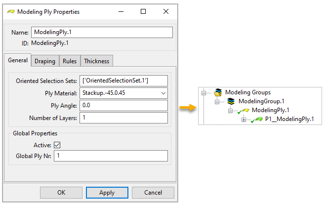
Create the bottom Modeling Ply by following steps 1 to 4 in Defining the Base Plate's Plies and using the specifications as shown in the image below.
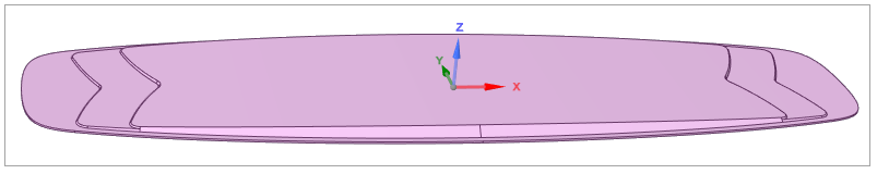
Click ModelingPly.1 in the Tree View (A), then select the Show Orientation icon from the toolbar (B) to view the Orientation of the ply.
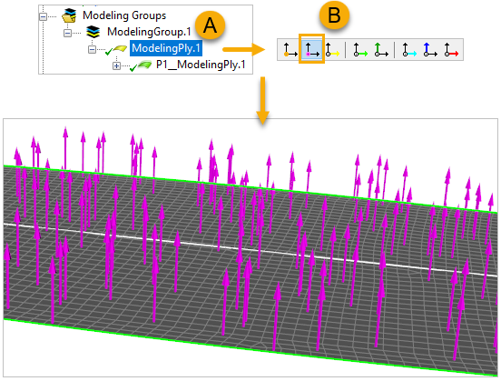
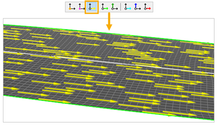
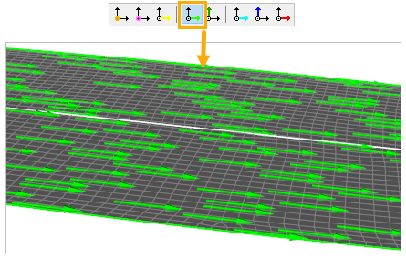
You can also view the Reference and Fiber Direction of the ply by choosing the appropriate icons from the toolbar.
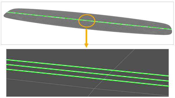
To create a section cut, follow the instructions in Defining a Section Cut and use the specifications as shown in the image below.
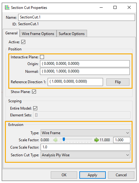
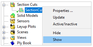
Note: You can show or hide the section cut in the model by right-clicking SectionCut.1 in the Tree View, then selecting Show or Hide.
Examine and verify the layering of the Modeling Ply, then close ACP (Pre).
This section guides you through creating the core with variable thickness using Virtual Geometry. This thickness will replace the placeholder thickness defined in step 3 of the earlier section, Modifying the Model and Mesh. Then, you will create another Modeling Ply on top of the core ply.
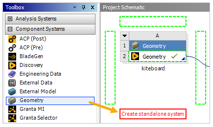
In Workbench, drag Geometry from Component Systems in the Toolbox and drop it onto the Project Schematic pane.
Double-click the title and rename Geometry to
kiteboard_core.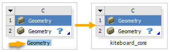
Right-click Geometry, select Import Geometry, then select Browse. Choose the kiteboard_core.stp file from the project folder.

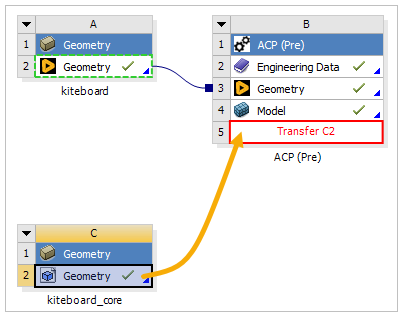
Click the C2 Geometry cell and drop it onto the B5 Setup cell to connect the two cells.
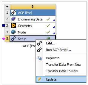
Right-click the B5 Setup cell and select Update. Double-click the cell to open ACP.
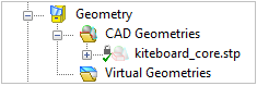
In the ACP's Tree View, expand Geometry and CAD Geometries. The kiteboard_core.stp geometry is automatically imported into ACP.
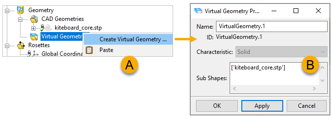
Right-click Virtual Geometries and select Create Virtual Geometry (A, below). In the Virtual Geometry Properties dialog, place the cursor in the Sub Shapes field (B), then select the kiteboard_core.stp CAD geometry from the Tree View. Click Apply, then click OK.
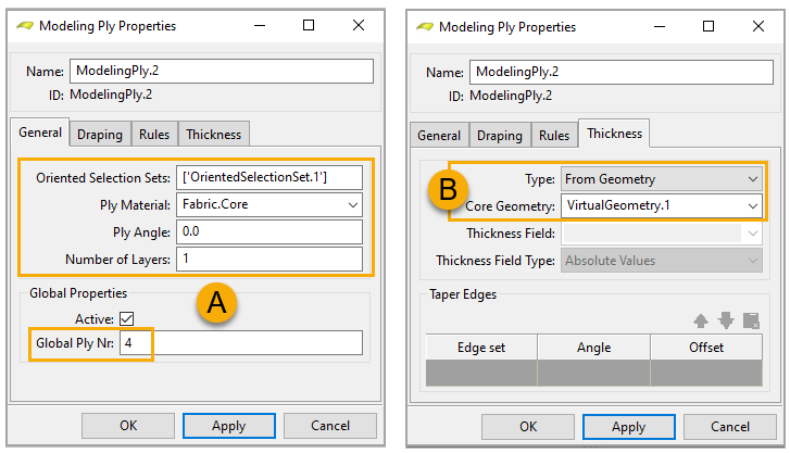
Create the core Modeling Ply by using the specifications as shown in the image (A, below). Switch to the Thickness tab, then define the Type and Core Geometry properties as shown (B). Click Apply, then click OK.
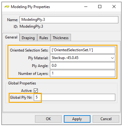
Create the top Modeling Ply by using the values as shown in the image below.
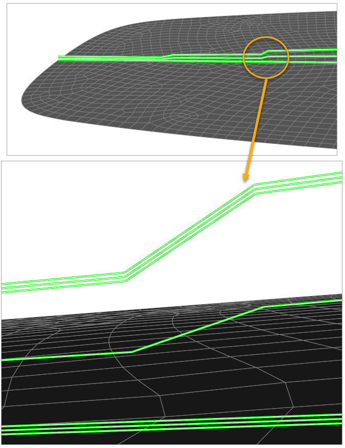
Right-click SectionCut.1 in the Tree View and click Update to visualize the three Modeling Plies.
Close ACP and go back to Workbench.