The following sections will guide you through setting up the project:
The project files are contained in a compressed file and can be downloaded here.
Once the download is complete, extract the compressed file. The folder contains two project archives: a from-start file and a solved file.
Start Ansys Workbench and Open the archive:
Kiteboard_FROM_START_<release>.wbpz
Save the Workbench project.
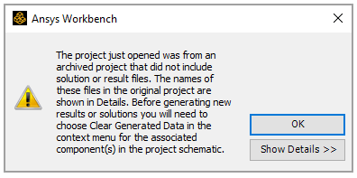
Note: To check the result in the solved archive file:
Start Ansys Workbench and Open the solved archive: Kiteboard_SOLVED_<Release>.wbpz.
Close the warning dialog if it pops up.
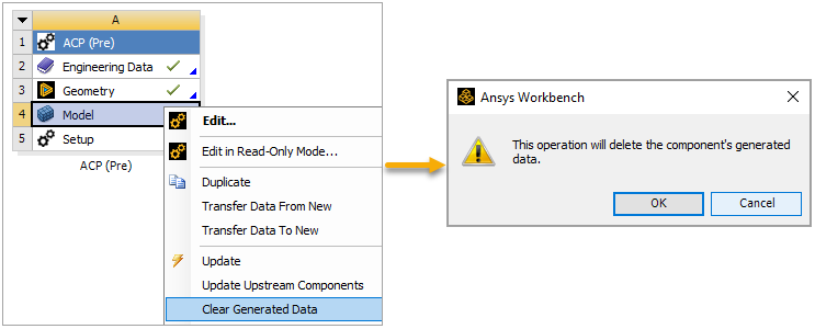
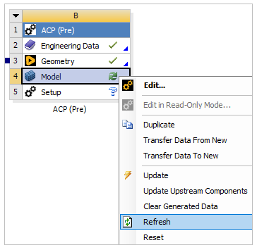
Right-click the Model cell in the ACP (Pre) system, select Clear Generated Data, then click OK when the warning dialog pops up.
Click Update Project on the project toolbar.
In this section, you will create a new material for the core of the kiteboard and add a predefined material from the Engineering Data Sources for the other layers.
In Workbench, right-click the Engineering Data cell in the ACP (Pre) system and select Edit.

In the Engineering Data pane, click the cell below Structural Steel and enter
Coreto create a new material.
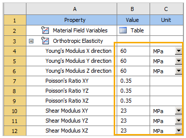
Drag Orthotropic Elasticity under Linear Elastic from the Toolbox and drop it onto the A1 Property cell.
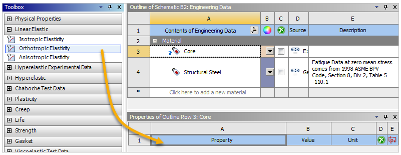
Define the Orthotropic Elasticity property values as shown in the image below. Change the Unit to MPa.
Follow steps 3 and 4 above to add Ply Type from Composite and define the Type as Orthotropic Homogeneous Core.

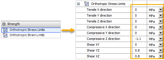
Follow steps 3 and 4 above to add Orthotropic Stress Limits from Strength and define the property values as shown in the image below.
Click the Engineering Data Sources tab (A, below), select Composite Materials under Data Source (B). Select Epoxy Carbon Woven (230 GPa) Prepreg under Contents of Composite Materials, then click the
 icon (C) to add the
material to the Engineering Data.
icon (C) to add the
material to the Engineering Data.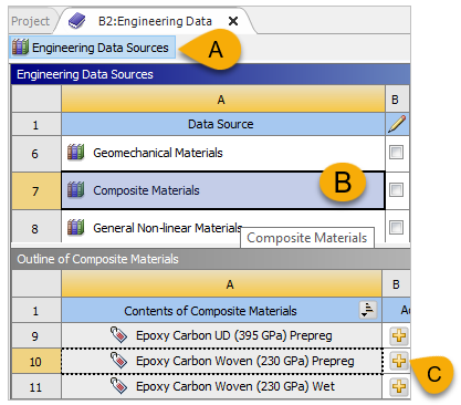
Note: Composite Materials is a repository with many typical materials (UD, woven, core, resin, and fiber) already defined to be used in ACP workflows. These materials should be considered only for educational purposes.
Click the Engineering Data Sources tab again (A, below) to go back to Engineering Data. Select the added material, Epoxy Carbon Woven (230 GPa) Prepreg (B), then change the Shear Modulus XY property value to
19500 MPa(C).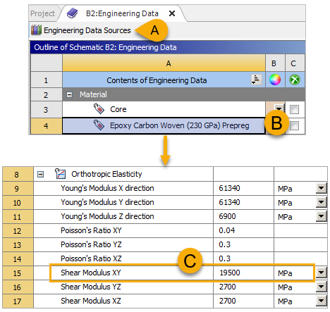
Close the Engineering Data tab.
Follow these steps to modify the model and mesh in Mechanical:
In Workbench, right-click the Model cell in the ACP (Pre) system and select Refresh. Double-click the cell to open Mechanical.
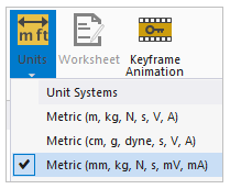
In Mechanical, switch to the Home tab. In the Tools group, select Units, then choose Metric (mm, kg, N, s, mV, mA).
In the tree Outline, expand Geometry, then click Geom\Kiteboard (A, below). In the Details pane, specify a Thickness of
1 mmand choose any material for the Assignment (B).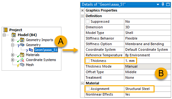
Note: The thickness definition and material assignment in this step are only placeholders. Parts defined as a composite lay-up later in ACP will replace these values, while correct material data for eventual non-composite parts, not defined in ACP (Pre), must be defined here.
Click any element in the model, then select the entire model by clicking the
 Select Parent Body icon.
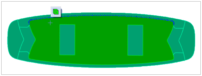
In the tree Outline, right-click Mesh, select Insert, then select Sizing (A, below). In the Details pane, define the Element Size as
10 mm.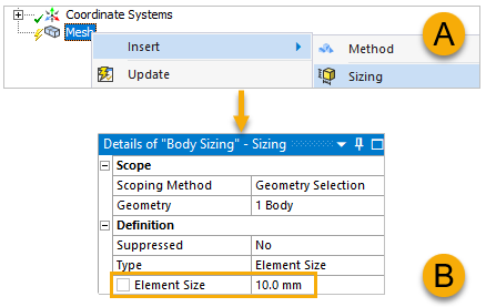
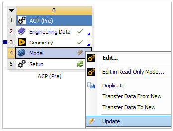
Close Mechanical. In Workbench, right-click the Model cell in the ACP (Pre) system and select Update.
This section guides you through defining two fabrics and a stackup that are used to model the kiteboard in later steps.
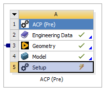
Double-click the Setup cell in the ACP (Pre) system to open ACP.
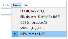
Select Units from the menu, select MPA (mm,t,s,N,C).
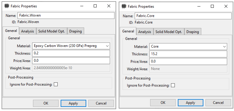
Create two fabrics by following steps 3 and 4 in Defining Fabrics and using the specifications shown in the image below.
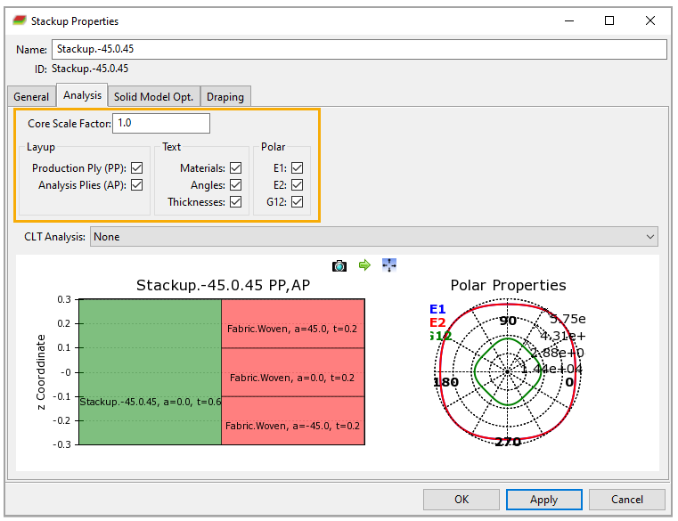
You will use a (-45°, 0°, 45°) stackup for the bottom and top plies. Follow the instructions in Defining Stackup Properties to define a stackup with the properties below.
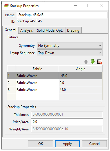
Switch to the Analysis tab of the Stackup Properties dialog. Specify the properties as shown in the image, then click Apply. Examine the stackup, then click OK to close the dialog.