In this section, you will create a rear binder, add boundary conditions, and simulate a force of 1029 N on the kiteboard in Mechanical.
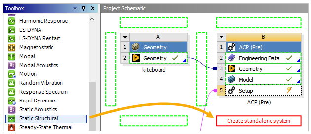
In Workbench, under Analysis System in the Toolbox, add a Static Structural system to the Project Schematic pane.
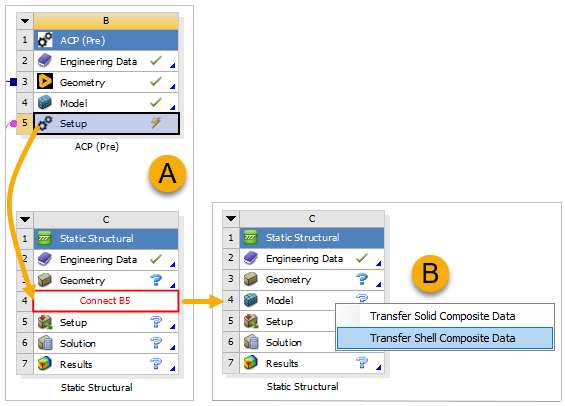
Click the B5 Setup cell and drop it onto the C4 Model cell to connect the two cells (A, below). When prompted, select Transfer Shell Composite Data (B).
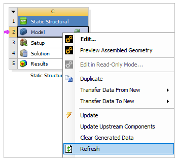
Right-click the Model cell in the Static Structural system and select Refresh, then double-click the cell to open Mechanical.
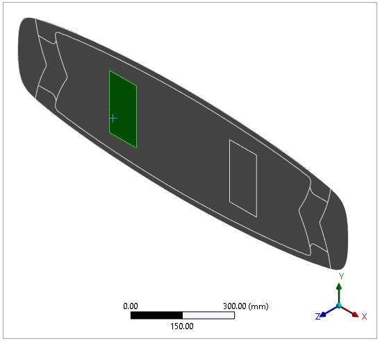
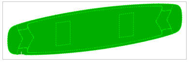
In Mechanical's Geometry window, select the model's face as shown in the image below.
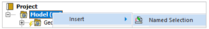
In the tree Outline, right-click Model, then select Insert and Named Selection.
Right-click the Named Selection, select Rename, then change the name to
rear_binder.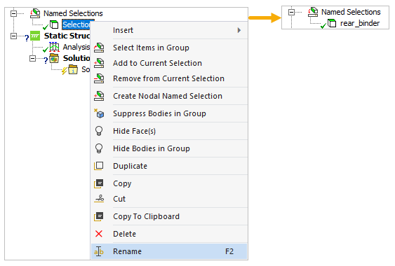
Create a Remote Point by right-clicking Model, then selecting Insert and Remote Point. Rename it to
support.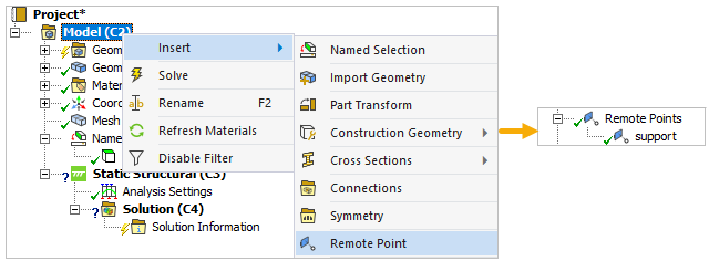
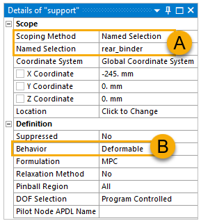
In the Details pane, select Named Selection from the Scoping Method drop-down menu, then select rear_binder for the Named Selection (A, below). Choose Deformable as its Behavior (B).
Create a Remote Displacement by right-clicking Static Structural, then selecting Insert and Remote Displacement. Rename it to
rear_binding_support.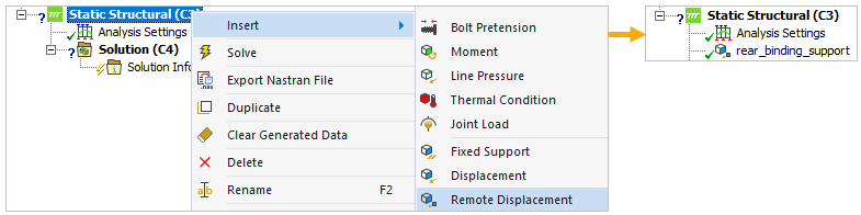
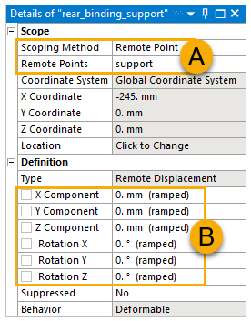
In the Details pane, define the Scoping Method and the Remote Points as shown in the image (A, below), then specify the other values like below (B).
Hold Ctrl and select all nine faces of the model.
Create a force by right-clicking Static Structural, then selecting Insert and Force. Rename it to
force_105Kg_1g.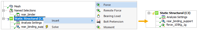
In the Details pane, select Components from the Define by drop-down menu (A). Specify the Z Component to
1029 N(B).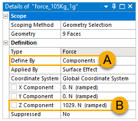
Note: The force of 1029 N corresponds to a 104.9 kg person landing on the kiteboard's rear end after a jump.
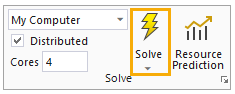
Click Solve in the Home tab or the Model tab.