


A user defined RVE consists of one or more phases and each of the phases consists of one or more solid bodies.
Set Up the User Defined RVE Type
In contrast to the predefined RVE types, you first need to provide some information about these phases.
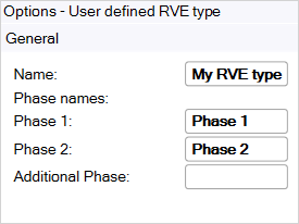
Name: Specify the name of the user defined RVE type.
Phase: Specify a name for each phase of the RVE.
Note: You can get back to these options by selecting the RVE model node in the Outline.
Create the User Defined RVE
First create or copy and paste the user defined geometry and then specify the options. See Hints for Importing Geometry for User Defined RVEs for more information.
Note: A coordinate system must already exist for the body in order to select it as the Element Orientation.
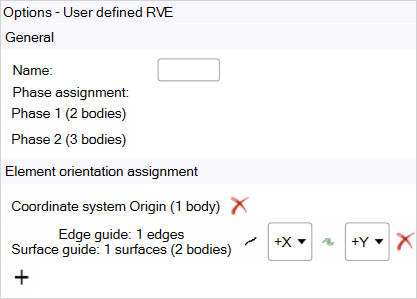
Name: Specify a name for the User Defined RVE.
Phase assignment: select the Phase you want to assign, then select the corresponding solid geometries in the working space and click Assign Bodies.
 .
.Element Orientation assignment: You can assign a coordinate system to one or more bodies. Alternatively, you can use edge and/or surface guides to define the Element Orientation for the elements of one or more bodies. To assign Element Orientation:
Click to add a new assignment.
This will activate the tool guides that allow you to define the Element Orientation assignment.
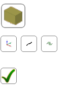
Click the Select Bodies icon
 , then select
the bodies on which you want to define Element Orientations.
, then select
the bodies on which you want to define Element Orientations.Set up a coordinate system, or Edge/Surface Guides:
Click the Select Coordinate System icon
 ,
then select the coordinate system which you want to use for
the Element Orientation assignment.
,
then select the coordinate system which you want to use for
the Element Orientation assignment.Note: This will clear any edge and surface guides as they can not be combined with coordinate systems.
Click the Select Edge Guide icon
 ,
then select the edges that you want to use as edge guides
for the Element Orientation assignment.
,
then select the edges that you want to use as edge guides
for the Element Orientation assignment.Note: This will clear any coordinate systems as they can not be combined with edge guides.
Click the Select Surface Guide icon
 ,
then select the surfaces that you want to use as surface
guides for the Element Orientation assignment.
,
then select the surfaces that you want to use as surface
guides for the Element Orientation assignment.Note: This will clear any coordinate systems as they cannot be combined with surface guides.
Click the Complete Element Orientation Assignment icon
 to finalize the Element Orientation assignment.
If you chose edge and/or surface guides, set the element axis that you want to correspond to the tangential vectors of the edge guide or the normal vectors of the surface guide:
Use the Edge Guide Axis combo box
 to define
to which axis of the Element Orientation the tangential
vectors of the edge guide should correspond.
to define
to which axis of the Element Orientation the tangential
vectors of the edge guide should correspond.Use the Surface Guide Axis combo box
 to
define to which axis of the Element Orientation the normal
vectors of the surface guide should correspond.
to
define to which axis of the Element Orientation the normal
vectors of the surface guide should correspond.
You can also select an existing Element Orientation assignment and use the buttons to change the assignment method. Click
 to remove the
assignment.
to remove the
assignment.
Note:You don't need to specify the coordinate system for all bodies. The global coordinate system will be used for all bodies that are not explicitly assigned an Element Orientation.
You can visualize the resulting Element Orientation; see Display Element Orientation.
The procedure to compute the Element Orientation in the cases of edge and surface guides works roughly as follows:
The edges and surfaces are discretized. For edge guides, the tangential vectors at these discretized points are used. For surface guides, the normal vectors at these discretized points are used. For simplicity, assume that the edge guide should define the X Axis and the surface guide should define the Z Axis.
Then, for each element covered by the assignment, the Element Orientations is determined as follows:
The application obtains the surface normal direction (N-vector) at a location on the Surface Guide closest to the element's centroid and aligns the specified axis (Z axis) with it.
The application obtains the tangential direction (T-vector) to the edge at a location on the Edge Guide that is closest to the element's centroid.
The cross-product of the N-vector and T-vector calculates the 3rd axis (Y axis).
The tangential, 2nd axis (X axis), is obtained by taking the cross-product of the N-vector and the 3rd axis.
In the case that only edge guides or only surface guides are defined, the application uses the surface normal direction or the tangential direction at a location that is closest to the element's centroid and uses this vector for the corresponding axis. The other axes are chosen arbitrarily. You should use this only for transversely isotropic constituent materials.
Note: For user defined RVEs, the only available parameter in a variable material analysis is temperature (provided that at least one of the constituent materials is temperature dependent).