


Useful Commands and Design Tools
This page describes Speos selection behavior and provides some useful commands, shortcuts and design tools that are frequently used during feature definition.
3D view Icons
It may appear sometimes that the icons in the 3D view disappear due to a wrong move.
To display them again:
- Select .
- Select the Popular tab.
- In the Control Options section, set Tool guide
position to another value than Not shown.
_Tool_Guide_Position.png)
Primary Selection Behavior
Standard commands are available and compatible with geometry, source and sensor selection.
- CTRL and shift commands are available for quick multi-selections.
- CTRL+A selects all bodies present in the scene.
- Box selection selects the set of highlighted bodies.
- ESC key allows you to exit/cancel a selection.
Each selection must be validated _Validation.png) for the
objects to be correctly imported in the Speos objects' list.
for the
objects to be correctly imported in the Speos objects' list.
Secondary Selection Behavior
The Secondary Selection allows you to preserve the selection when switching through Speos tools (whereas the Primary selection is currently modified as soon as an object is edited with a selection command):
- Hold ALT key to make a secondary selection (appearing in blue).
- Hold CTRL+ALT to make a secondary multiple selection.
_Secondary_Selection.png)
- To check the status of primary and secondary selection, mouse-over the bottom tool bar as
follows:
_Mouse_Over__Selection_Status.png)
: Hold the ALT key and click
Validate
._Validation_Secondary_Selection.png)
Simulation Panel Selection Behavior
In the Simulation Panel, you can create folders and sub-folders under each Speos object family. The Select folder content command allows you to select only the direct content of the folder.
To select the content of a folder, right-click the folder and click Select folder content.
_Select_Folder_Content.png)
Disable Preselection
The Disable preselection command removes the preselection (temporary highlight) of 3d view elements in order to gain performance on the interface reactivity.
To disable the preselection, right-click anywhere in the 3D view, and check Disable preselection.
Revert Selection
In case you lose your selection or want to go back to a previous selection, use the Revert
Selection command _Revert_Selection.png) (bottom right of SpaceClaim interface) to restore the state of your previous or lost selection.
(bottom right of SpaceClaim interface) to restore the state of your previous or lost selection.
Grouping
Groups or Named Selections allow you to better organize your project and save time during element selection. They also allow you to save memory when working with data separation by layer as groups represent one layer in the simulation result.
The grouping function is available for any Speos object (sources, sensors, geometries, OPD face groups etc.).
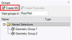
Grouping using Create NS
- To create Named Selections, select objects in the 3D view, from the Structure or from the Simulation panel.
- In the Groups panel click Create NS.
Grouping using the Contextual Menu
From the Simulation panel, right-click a node, folder, or sub-folder, and select Create Named Selection.
_Create_Named_Selection.png)
A named selection of the folder content is created in the Groups panel with the name of the folder.
After Grouping
-
Selected for a Speos feature (a simulation for example) by either using the 3D view selection tools
_3D_View_Selection_Tools.png) or the contextual menu of the
definition panel.
or the contextual menu of the
definition panel.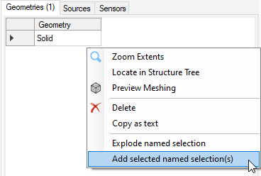
Identified from the groups or the simulation panel at any time.
In the Groups panel, just hover over a named selection to see the Speos objects it contains being highlighted in the Simulation panel. Inversely, from the Simulation panel, right-click a Speos object and click Show the named selection(...) to highlight its associated group in the Groups panel.
Note: Hidden geometries belonging to a group are not highlighted in the tree when selecting the group.-
Exploded back into a set of separate objects.
When a group is exploded from the Groups panel, each object that was in the group is placed in its own group. The new group names are based on the parent group.
When a group is exploded from the Definition panel, the group is replaced by the set of objects it was containing.
Note: For more information on grouping, consult the SpaceClaim documentation.
Speos Useful Commands
Several shortcuts and commands are available in Speos to ease navigation and feature definition.
The following list is non-exhaustive but describes the most frequently used commands and shortcuts.
- The Tab key allows you to switch lines in the definition panel.
- The up and down arrow keys allow you to flip through the choices of a drop-down list without unrolling it.
- F4 key (or Speos Edit button from the ribbon) allows you to enter/exit a feature edition mode.
- ESC key allows you to exit a feature edition mode.
- CRTL+N allows you to create a new design.
- CTRL+O allows you to open a project.
- CTRL+G allows you to create a new Named Selection containing the current set of selected (highlighted) objects.
Design Tools
When designing the optical system, you might need to create points or axis systems to place the geometries or features in the scene.
Points
You can use the point creation tool _Point_Creation.png) (available from the Design tab) to place points in the scene.
(available from the Design tab) to place points in the scene.
To place the point on the right plane/object, you can sketch on a plane or directly in 3D mode:
- To sketch on a plane, place your cursor on a line, edge or surface to automatically change the plane axis.
- Press D to switch to 3D mode and compute the point on a geometry.
3D mode
Plan mode
Axis Systems
When working with Speos features, it might be useful to create and compute axis systems on specific points of interest.
Axis systems allow to better visualize the position and orientation of pieces of a system. It can also be used during feature definition to select directions and origins.
Use the origin
_Axis_System_Origin.png) creation tool to compute a point
and its associated axis system (available from the Design tab).
creation tool to compute a point
and its associated axis system (available from the Design tab).
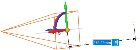
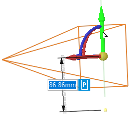
Move
With the Move option (available from the Design tab), you can move and rotate sensors on any of their axes.
You can also move geometries, even when a source is defined on it.
If you want more information, see Move option from SpaceClaim documentation.
 |
 |
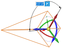 |
| Move on X Axis | Move on Y Axis | Rotation |
Locking and Unlocking Objects
You can lock the different objects (Surface, Body, Point, Line, Axis System, Plane) available in the Structure tree so they cannot be changed therefore preventing unintended modifications.
Locking Objects
- In the Structure tree, right-click an object.
Select Lock.
The Lock command is checked.
_Lock_Unlock.png)
If an object has sub-components, sub-components are also locked.
Unlocking Objects
- In the Structure tree, right-click a locked object.
Select Lock.
The Lock command is unchecked.
If an object has sub-components, sub-components are also unlocked.