Graphical User Interface
This page gives a general overview of Speos interface and helps to better understand the working environment.
General Interface
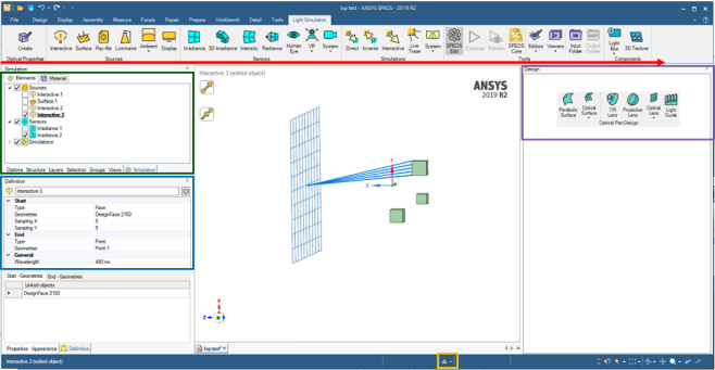
- Speos Features: Work flow based layout.
- Simulation panel (green section): All Speos features are stored here except Optical Part Design features.
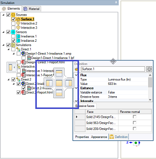
- Definition panel (blue section): Displays the parameters of the active Speos feature.
- Design panel (purple section): Displays Optical Part Design features and is only displayed when a feature is created. The Optical Part Design menu is stored in the Design tab.
- Status Information (yellow section): Warnings, errors and notifications are available here.
Interface Highlights
-
From the Simulation panel, you can visualize the features' state and control their visibility in the 3D view.
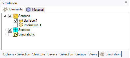
A feature is:
- bolded and underlined when it is in edition. The feature is then considered as active.
-
in error when an exclamation point appears after the feature's name.
Note: A feature appears in error if it is not defined or has not been correctly defined. - hidden in the 3D view when the check box is clear.
-
From the Simulation panel, you can create unlimited folders and sub-folders under each Speos object family and organize objects as want.
_Tree_Create_Folder.png) Tip: You can drag and drop Speos objects in and out of the folders created and to reorganise them inside a folder (except for Materials).
Tip: You can drag and drop Speos objects in and out of the folders created and to reorganise them inside a folder (except for Materials). - The Definition panel is dedicated to Speos features.
-
The Design panel only appears when an optical design feature is created.
Tip: All panels of the interface can be moved. Simply drag a panel away from a dockable location to drop it where you want to place it.To restore the original layout at any time, go to and in Appearance, click Reset Docking Layout.
Note: Modifying the Speos tree panels position is not kept when reopening Speos after opening a SpaceClaim session without Speos.