Creating an Observer Sensor
Creating an observer sensor allows you to create a specific view point from where you can observe the system. This sensor is useful to visualize the optical system from user defined points of view.
Note: If your computer has enough memory, deactivate the VR Sensor Memory
Management
(accessible from the general options)
for better performance.
To create an Observer Sensor:
-
From the Light Simulation tab, click VR
_Sensor_VR.png) > Observer
> Observer _Sensor_Observer.png) .
.
-
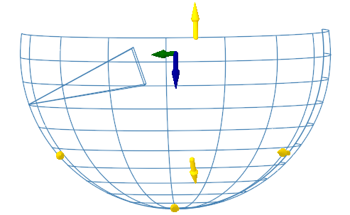
In the 3D view, define the Axis system of the observed object.
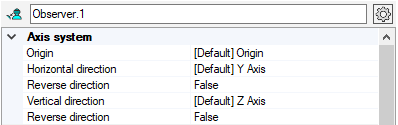 Note: With the Observer Sensor, the axis system does not define the sensor's position but the observed object/scene position. A sphere is then generated around the defined origin allowing you to adjust the sensor's position by adjusting the sphere itself.
- Click
_Origin_Point.png) to select an origin
point.
to select an origin
point. - Click
_Sensor_Lidar_Horizontal_Direction.png) to
select a line defining the horizontal direction.
to
select a line defining the horizontal direction. - Click
_Sensor_Lidar_Vertical_Direction.png) to
select a line defining the vertical direction.
to
select a line defining the vertical direction. - or click
_Axis_System_Autofill.png) and select a coordinate
system to autofill the Axis System.
and select a coordinate
system to autofill the Axis System.
Important: Make sure the sensor is not tangent to a geometry.Note: Make sure no geometry intersects the sensor. Otherwise you may generate unexpected black result in CPU simulation.Note: If you define manually one axis only, the other axis is automatically (and randomly) calculated by Speos in the 3D view. However, the other axis in the Definition panel may not correspond to the axis in the 3D view. Please refer to the axis in the 3D view. - Click
-
In General, in Distance, adjust the radius of the
sphere to narrow or widen the global field of vision.
_Sensor_Observer_General.png)
-
In Wavelength, define the spectral range the sensor needs to
consider:
_Sensor_Wavelength.png)
- Edit the Start (minimum wavelength) and End (maximum wavelength) values to determine the wavelength range to be considered by the sensor.
-
If needed, in Sampling, adjust the number of wavelengths to be computed during simulation.
The Resolution is automatically computed according to the sampling and wavelength start and end values.
-
In Observer locations, define the sensor's position on the sphere around
the target point:
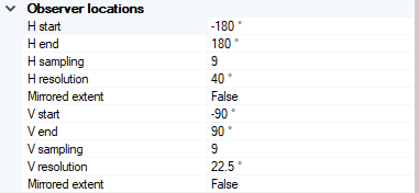 Tip: You can use the 3D view manipulators to adjust the Vertical and Horizontal Start and End positions of the sphere.
- Set the observer location horizontally by adjusting H start and end values.
- Set the observer location vertically by adjusting V start and end values.
-
Adjust the V and H sampling.
The resolution is automatically computed.
-
In Size, adjust the sensor's size:
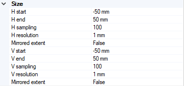
- Set the horizontal size of the sensor by adjusting H start and end values (in mm).
- Set the vertical size of the sensor by adjusting V start and end values (in mm).
-
Adjust the V and H sampling.
The resolution is automatically computed.
Note: Speos supports a maximum resolution of 23170 * 23170 pixels.
-
In Optional or advanced settings
_Speos_Options.png) :
:_Sensor_Observer_Optional_Advanced_Settings.png)
- If you do not want to display the vision field (the sphere), set Show vision field to False.
- If you activated the vision field, in Preview, you can adjust the
active vision field horizontally and/or vertically to place the observer on a specific
location.Note: When defined, this position is used as the default viewpoint for the Automatic framing
_Sensor_Automatic_Framing.png) option.
option.