
Operations on Components and Design Objects in the Schematic Editor
Right-click a component or other design object in the schematic editor to select the object and open a context menu. Some context menu examples are shown below. Default commands (typically those that are invoked when you double-click an object) are at the top and bold.
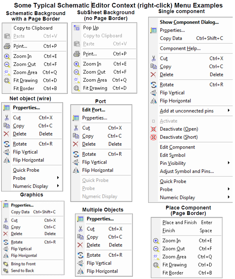
The following describes the possible Schematic Editor context menu commands.
- Properties – Opens the Properties dialog box for the selected component.
- Component Help – Opens the help topic for the selected component.
- Show Component Dialog... – Opens the component Parameters dialog box for the component.
- Add at unconnected pins – Adds either Page Connectors, Interface Ports, or Grounds to unconnected pins of the component.
- Cut – Deletes the selected component or wire segment, and retains a copy for pasting into a schematic in the same application.
- Copy – Creates a local copy for pasting into a schematic in the same application.
- Delete – Deletes the component.
- Rotate – Rotates the component 90 degrees counterclockwise. (See Rotate in Drawing Operations.)
- Flip Vertical – Flips the component in the Y-direction. (See Flip Vertical in Drawing Operations.)
- Flip Horizontal – Flips the component in the X-direction. (See Flip Horizontal in Drawing Operations.)
- Bring to Front – Moves the selected object to the front of the drawing. (See Bring to Front in Drawing Operations.)
- Send to Back – Moves the selected object to the back of the drawing. (See Send to Back in Drawing Operations.)
- Activate – Restores a deactivated component to the circuit.
- Deactivate (Open) – Temporarily converts the component into an open circuit. This is displayed graphically with a red X over the circuit element.
- Deactivate (Short) – Temporarily converts the component into a short circuit. This is displayed graphically with a circled red X over the circuit element. Deactivating (short) a component with multiple conservative pins will connect all the conservative pins to the same net. Deactivating (short) a block (which contains non-conservative pins) does not work the same as the circuit component, and the output of the shorted block will be 0.
- Edit Component – Lets you edit the component using the Component Editor.
- Edit Symbol – Lets you edit the component symbol using the Symbol Editor.
- Copy as New Design – Present if the component represents a subcircuit. Lets you copy hierarchical designs (subcircuits) such that the pasted copy is independent of the original source design. This menu item is also present in the context menu for a subdesign in the Project Manager pane. (See also: Copying a Twin Builder Design into Another Design)
- Edit Model – Lets you edit the component model using the appropriate model editor: SML Model Editor, VHDL-AMS Model Editor, C-Model Editor, SPICE Model Editor. The Message Manager informs you if the model is not editable.
Alternatively, you can open the model for editing. Right-click the model symbol in the Project Manager Project tab, and select Model from the context menu.
- Pin Visibility – Lets you toggle visibility of individual component pins.
- Adjust Symbol and Pins – Lets you move unconnected pins around the circumference of the bounding rectangle of a selected component (such as coupling components and components that represent subcircuits). Also lets you resize the bounding rectangle. (See Adjusting Symbols and Pins for additional information.)
- Revert to default symbol – present if changes have been made to a component symbol using the Adjust Symbol and Pins command. Lets you revert to the component’s original symbol. (See Adjusting Symbols and Pins for additional information.)
- Push Down – Moves down one level in the project design.
- Pop Up – Moves up one level in the project design.
- Quick Probe – Inserts a 2D rectangular plot-on-schematic of a parameter in the list of defined outputs for the component. Quick Probe first looks for V if it exists, then I, then the first quantity not starting with a lower case “d”, then the first quantity (in that order).
- Probe – Inserts a 2D rectangular plot-on-schematic of a component parameter chosen from a list of defined outputs for the component. Default parameter types can be selected on the Schematic Editor Options>Twin Builder Schematic panel.
- Numeric Display – Adds a data table to the schematic. You can choose which quantity of the selected component to display from the submenu. By default, only the last value calculated is displayed.
- Copy to Clipboard – Creates a global copy on the clipboard for pasting into a different application.
- Paste – Puts the local object from the previous copy or cut into the schematic.
- Print – Prints the schematic in the active window.
- Zoom In – Decreases the area of the schematic in the view.
- Zoom Out – Increases the area of the schematic in the view.
- Zoom Area – Specify the new view area. Click to specify the upper left and lower right corners.
- Fit Drawing – Changes the view to include all the objects currently present.
- Fit Border – Changes the view to include the page border. (See Page Borders Tab.)
Right-click a component in the Components tab of the Component Libraries window to open a menu containing these commands:
- Add to Favorites – Adds the component to your list of frequently-used components (see Favorites and Most Recently Used Components).
- Place Component – Attaches the component symbol to the cursor for placement in the schematic (see Placing Components on a Schematic).
- Edit Component – Opens the Component Editor dialog (see Editing Component Libraries for details).
- View Component Help – Opens the help topic for the component (see Help for Components).
- Load Example – Loads the example project associated with the component.