
Editing Component Parameters
You can use Twin Builder to enter component parameter values in multiples of standard SI units such as millivolts, nanoamperes, and kilometers, as well as in non-SI units such as pounds per square inch, degrees Fahrenheit, and feet. Twin Builder performs all of the necessary unit conversions, reducing the time needed to calculate component parameters.
Component parameters that are physical quantities can be assigned expected units of measure. These default units are the ones associated with the parameters during simulation. In addition to the expected (default) unit of measure, an additional set of units known as “used units” can also be specified for the same physical quantity. For example, the amplitude of a force source may have an expected unit of Newtons and a set of “used units” that includes pounds and dynes.
Twin Builder internal models have predefined default units for their parameters. Parameters of user-defined models such as C-Models and text macros can be assigned expected units when they are created.
To display the editable parameters of a component, either right-click the component and select Display Component Dialog, or double-click the component. A typical component Parameters dialog box is shown below.
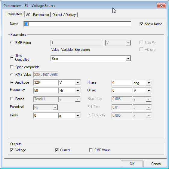
A component’s Parameters dialog box opens with its left-most tab selected by default; and with the component instance Name selected.
Twin Builder assigns a unique Name to each component instance you place on a schematic.
- If you choose to rename a component instance, do not duplicate the name of any other component instance (for example, R1 and r1). Duplicate instance names result in netlist errors when attempting to compile a circuit prior to analysis.
- The first character of a name must always be a letter.
- Vowel mutations (for example, umlauts) are not allowed.
- Spaces are not allowed.
The parameters and associated units of measure shown in the component dialog boxes vary by component. The dialog box may also contain additional parameter settings tabs - depending on the component type. It also contains an Output/Display tab on which you can enable parameters as outputs, and control how they are displayed on schematics.
- Component Properties dialog boxes also provide access and control of the parameters shown in the Parameters dialog boxes.
- You must use the Properties dialog boxes to edit parameters of components that do not have a Parameters dialog box.
Use the various radio buttons, check boxes, drop-down lists, and text boxes to edit parameter values and - where applicable - to select the unit of measure. When new units for a component’s parameters have been selected and the component is simulated, Twin Builder converts quantities expressed in the “used units” to equivalent quantities of the default (expected) units. In other words, component parameters can be expressed in units from different systems of measurement, and the simulation still produces accurate results.
You can also specify parameter values via input from an external component. To do this, select the Use Pin check box next to the desired parameter. The parameter’s value field is grayed-out to show that the value of the parameter will now be determined by the component to which the pin is connected.