
Workflow of an HFSS 3D Layout Design
Setting up an HFSS 3D Layout design is very similar to setting up an HFSS design or an HFSS-IE design. To set up an HFSS 3D Layout design, follow this general procedure. After you insert a design, you do not need to perform the intermediate steps sequentially, but you must complete them before you generate a solution.
Defining a solution setup enables HFSS 3D Layout to compute a solution for a design. You can define multiple solution setups for the same design. If you right-click in on the Project Manager window and select Add Nexxim Solution Setup , select a type of analysis to set up, which opens a solution setup window. You can specify multiple settings in the solution setup window for computing a solution for a design.
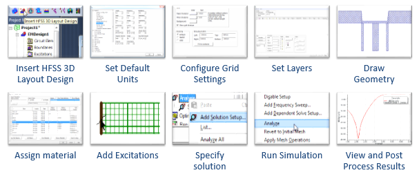
- Insert an HFSS 3D Layout design into a project.
- Draw the model geometry, specifically:
- Create the metal and dielectric layers of the design.
- Assign a thickness, roughness, elevation, and material to each layer.
- Draw the geometry of the signal layers.
- If applicable, create a cavity between two infinite negative signal planes.
- Assign material characteristics
- Define the ports or incident waves in the model.
- If applicable, insert an external device, an N-port, with known S
- parameters into your design. - Specify how to compute the solution by adding a solution setup.
- (Optional) Set up any Optimetrics you want to run.
- Run the simulation. HFSS 3D Layout computes the current inside the structure.
- View the solution results, post-process results, and reports, and create field overlays.
Some of these tasks may not be applicable to your designs. Not all designs require cavities or N-ports.
After a period of idleness of 10 minutes, HFSS gives up its license. A renewal of activity automatically requests a license. Such idle notifications do not occur during simulations.