
Choosing Grid Settings
The grid displayed in the Modeler window is a drawing aid that helps to visualize the location of objects.
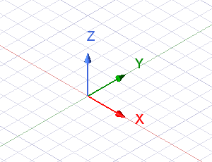
For Cartesian grids, the location of points on the grid are defined by intersections of planes that are perpendicular to and along the x-, y-, and z-axes. The division (the distance between neighboring parallel planes perpendicular to the same axis) can be set.
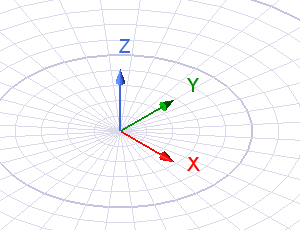
For polar grids, the location of points on the grid are defined by intersections of planes that are perpendicular to the local radius and angle coordinates. The division (the distance between neighboring parallel planes perpendicular to the same radius and angle) can be set.
Grid spacing is set according to the current project's drawing units. You can control the following aspects of the grid:
- Type (rectangular or circular)
- Style (dots or lines)
- Grid Extent (minimal for existing objects or as a plane)
- Density
- Spacing
- Visibility
- Snap settings
- Grid plane