
Creating a Face Coordinate System
- Select the object face upon which you want to create the face CS. The CS face can be planar or curved.
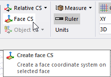
- Click Modeler> Coordinate System> Create> Face CS or, on the Draw ribbon tab, click the Create Face CS icon.
- Select the Origin in one of the following ways:
- Click a point on the selected face to define the Origin. If the point is not on the face, you will receive an error message.
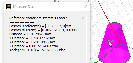
The Measure Data window shows the current cursor coordinates. The cursor shape will change to identify grid points, vertices, edge center, face center, quadrant, and arc center points, but you can click any point on the selected face.
- Type the point's coordinates in the X, Y, and Z text boxes on the Status Bar.
- Click a point on the selected face to define the Origin. If the point is not on the face, you will receive an error message.
- Specify the positive X-axis direction in one of the following ways:
- Click a point on the selected face. If the point is not on the face, you will receive an error message.
- Type the coordinates of a point that is relative to the previously selected point in the dX, dY, and dZ text boxes, where d is
the distance from the previously selected point.
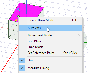
- Right-click in the Modeler window and select Auto Axis from the shortcut menu. The modeler selects the X-axis based on the principal curvature of the face or the dimensions of a flat face. The axial direction of a curved face or the long dimension of a flat face is selected as the X-axis direction.
You do not need to specify the Y or Z axes. The modeler assumes that the Z-axis is normal to the object face and the Y-axis is automatically calculated to be perpendicular to the XZ plane.
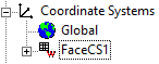
The new face CS is listed in the History Tree under Coordinate Systems. It automatically becomes the working CS; objects that you draw hereafter will be referenced to the coordinates of this face CS. Default planes are created on its XY, YZ, and XZ planes.
Only operations listed in the History Tree before the face CS's creation will affect the face CS and, in turn, affect objects dependent upon that face CS. A face CS, or any object created on it, is not affected by operations that occur after the face CS is created. Also see the Move CS to End command.
For example, suppose you create a box, then a face CS on a face of the box, and then a cylinder on the face CS. If you then edit the box's dimensions in the docked Properties window, the cylinder will move accordingly. But if you rotate the box using the Edit> Arrange> Rotate command, the box will move, but the cylinder will not move (because the rotation operation occurs later in the History Tree).