
Specifying Initial Mesh Settings
You can specify the initial mesh settings, including the surface approximation and the meshing approach. Initial Mesh Settings apply to all objects; however, if you apply separate surface approximation mesh operations to specific objects, the object settings take precedence over the general setting.
When you have defined mesh linking between a source and target design, all parameters within the Initial Mesh Settings dialog box are ignored for the target design. The mesh is copied from the source design without modification.
For most designs, you can let the solver automatically choose which of two meshing approaches to take. Each solver predicts which one gives the best results, balancing mesh reliability, speed, quality, size and design characteristics.
In most cases,
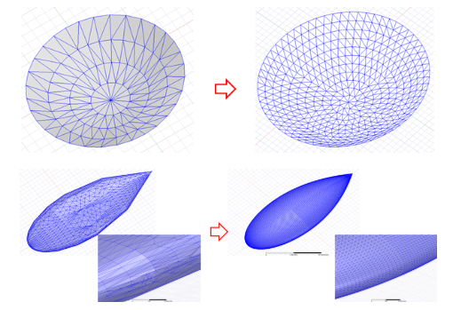
If the model contains IE Regions, the TAU mesher uses a surface mesh routine to detect which curve faces should be remeshed, rather than using the faceting triangles. This produces a high quality mesh, uniform, including the top, sides and bottom. (See the following figure for examples of the benefit.) Other faces that cannot be remeshed still get faceting triangles from the modeling kernel. In the final output, the remeshed surface mesh and faceting surface mesh are coupled to ensure the mesh is watertight and conformal.
In a few cases, you may decide to override the automatic choice and designate the mesher to use. To do so:
- Access the Initial Mesh Settings one of two ways:
- Select
- In the Project Manager, right-click Mesh, and select Initial Mesh Settings from the shortcut menu.
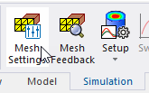
- On the Simulation tab of the ribbon, select Mesh Settings.
-
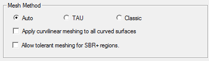
- Auto – the solver automatically selects the mesher. This is the default setting. In most cases, HFSS uses TAU and HFSS-IE uses Classic mesh.
- TAU – only specific curve faces will be remeshed (for example,
equation-based axisymmetric faces). If a curve face connects to non-remeshed curve faces, the
curve face will not be remeshed. If a curve face cannot be remeshed, faceting triangles will be
used as the surface mesh. Mesh quality depends on how the faceting triangles are made. If the
surface mesh is generated by TAU, it shows in the profile as Mesh TAU (Surface).
- Classic – based on the version 11 mesher.
- For
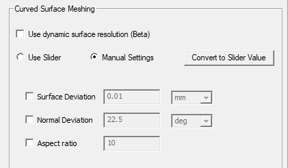
- Under Curved Surface Meshing, you can choose to Use dynamic surface resolution, select Use Slider or specify Manual Settings.
- If you choose Manual Settings, the window changes to show text fields. See: Modifying Surface Approximation Settings.
- Surface Deviation – the distance between the true surfaces of the selected faces and the meshed faces.
- Normal Deviation – the angular distance between the normal of the true surface and the corresponding mesh surface.
- Aspect Ratio – determines the shape of the triangles. The higher the value, the thinner the triangles. Values close to 1 will result in well-formed, wide triangles.
- Clicking Convert to Slider Value converts the manually entered values to an equivalent slider setting, and returns the panel to the slider view.
- To make your choices the default, use the Save as default check box.
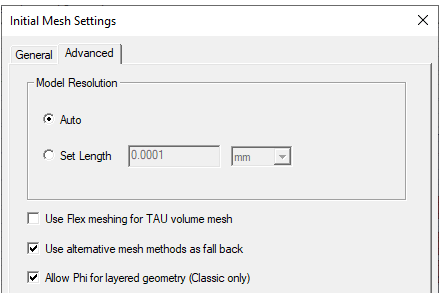
- The Advanced tab lets you optionally specify a Set Length for Model Resolution. This is for experienced users who have a good understanding of how particular values will affect their models. In general, the Auto setting provides good results.
- Use Flex meshing for TAU volume mesh enables a version of the TAU mesher that will rarely fail to generate a mesh. In most cases, the TAU Flex mesh is as accurate as traditional TAU or Classic meshes. However, for some complex models with bad translation or poorly defined surfaces that would fail to produce a strict mesh on all objects, relaxed tolerances will be applied. In these cases the user should review the mesh to evaluate whether it is acceptable for simulation. See TAU Flex meshing for more details.
- Use legacy faceter for TAU volume mesh – By default, TAU uses the latest faceter to generate geometric model for meshing. Occasionally, the mesher may fail, and TAU will automatically fall back to use the legacy faceter to make a second attempt. In such cases, directly using the legacy faceter can get the mesh in the first attempt so total meshing time will be saved. The legacy faceter is not actively maintained by Spatial and will be retired soon. This option should be used only as a last resort.
- If your selected mesh method (Classic/TAU) failed to generate initial mesh, the solver can either stop or fall back on alternative mesh methods if you select Use alternative methods as fall back. You can also select Phi for layered geometry (Classic only). For example, specifically, the mesher might go like this: When mesh method is TAU: TAU(>Phi)>Classic. When mesh method is Classic: Classic(>Phi)>TAU. Note: the options do not affect the Auto mesh setups.
- Click OK to apply your choices.
The Initial Mesh Settings window appears, with the General tab selected.

If the design contains an SBR+ Region, the Initial Mesh Settings window includes another option to Allow tolerant meshing for SBR+ regions. This is because the SBR+ ray-tracing solver has relaxed surface meshing requirements relative to other HFSS solvers. If an imported scattering geometry for the SBR+ region contains anomalies that make it too time-consuming or impossible to use Auto (default) meshing, the tolerant meshing option should be tried, as it will often yield a successful mesh in cases where Auto won't. On the other hand, if the imported geometry is clean and Auto meshing works well, tolerant meshing can sometimes result in an excessive number of surface mesh triangles that increase SBR+ solution time. The best meshing option for SBR+ is very dependent on the quality of the input geometry, so users need to consider both approaches and choose the one that works best for a particular scattering geometry.
Dynamic Meshing eliminates mesh file generation during SBR+ simulations, and it makes the simulations faster. Importing a lightweight geometry into an SBR+ design disables editing for the Use Dynamic Meshing option for the Initial Mesh Settings, and Use Dynamic Meshing is always On. If the design does not include Lightweight geometries, you may select Dynamic Meshing which skips generating mesh file during simulations. Dynamic meshing either uses the geometry triangulation in the case of the light weight geometry, as the mesh for the SBR+ solver.
The consolidation of surfaces into a conformal mesh is skipped for dynamic and tolerant meshing, including for light weight geometries. This can lead to overlapping surfaces in SBR+ simulations. The user should carefully avoid overlapping surfaces or objects as SBR+ can produce unexpected results.
If you select Use dynamic surface resolution, the Manual Settings option is disabled.
The slider includes a visual representation of your choice, ranging from a Coarse Resolution (with a Small Mesh Count) through a nine position scale to a Fine Resolution (with a Large Mesh Count. Here, "Mesh Count" refers to the number of elements comprising the mesh.
Selecting Use dynamic surface resolution in the Curved Surface Meshing section specifies the best-practice mesh operations over the geometric models. This mesh operation will support 3D volume mesh and surface mesh in all products. The default mesh operations or user-defined mesh operations may or may not be replaced by the optimized mesh operations with model analysis. In general, large curve faces, curve faces with small gaps, or skewed cables get more smooth curvature representation while small curve faces, such as fillets, small curve objects, and so forth, get relatively coarse triangulations so that the overall mesh count will be reduced.
If you select dynamic surface resolution, you can optionally use the slider bar to adjust surface representation levels as: coarse (1-3), normal (4-6), and fine (7-9). You can also adjust the surface representation level for a specific group of faces by specifying slider bar, as described in Modifying Surface Approximation Settings.
Use the check boxes to enable the fields and specify values:


The settings will be applied to the initial mesh generated.