
Assigning IE Regions
For driven modal and driven terminal solutions you can assign dielectric or conducting objects or sheets as IE Regions to be solved with the IE Solver as part of a hybrid simulation approach, using the advantages of the FEM and Hybrid Region solvers. IE Regions use an integral equation solver (sometimes called method of moments = MoM) and solves for the currents on surfaces of objects. It creates a triangular surface mesh on all objects - it solves for the currents or equivalent currents on conducting and dielectric objects. In general, HFSS uses the finite element method (FEM) to solve for the electromagnetic fields in the solution region. It meshes over the entire solution volume (other than areas assigned as one of the Hybrid Regions) and solves for the electric field throughout that volume.
To use Hybrid IE Regions, the solution type must be HFSS with Hybrid and Arrays.
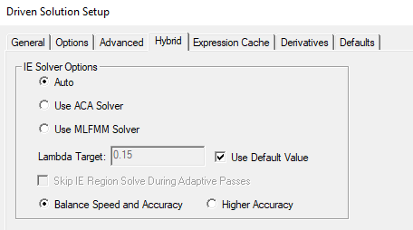
If you assign Hybrid regions, you can use the Hybrid tab in the Advanced Solution setup to specify the IE Solver type as ACA (the traditional method) or as MLFMM, which is superior than ACA for models with large FE-BI surfaces, and also works for IE regions. The default choice is Auto, in which the choice is made based on the characteristics of the design. See Guidelines for Choosing Between ACA and MFFMM IE Solver Options.
To Assign an IE Region
To use Hybrid IE Regions, the solution type must be HFSS with Hybrid and Arrays.
You must select an appropriate object or face in order to enable the menu.
- Select the object you want to assign as an IE Region, and use one of the following menus:
HFSS>Hybrid>Assign Hybrid>IE Region
Right-click in the Modeler window and select Assign Hybrid>IE Region.
Select the Hybrid Regions icon in the Project
tree, right-click, and click Assign>IE
Region.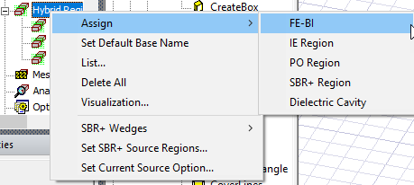
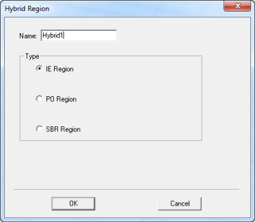
The dialog for Hybrid Region opens, showing the default name and type selection as IE Region. Because you may decide to change an assignment for IE Regions, and PO Regions, the dialog shows these types as radio button selections.
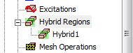
- When you OK the dialog box, the assignment
appears in the Project tree under Hybrid Regions.
Applications and Technical Considerations for Using IE Regions
Application areas for IE Regions include:
- Radar cross section (RCS)
- Antenna placement (for example, antenna on a vehicle)
- Stand alone antennas
- Coupling. EMI/EMC
- When a layered impedance boundary touches a dielectric to model paint on fascia which is important for ADAS radar simulations
In assigning IE Regions:
- 3D objects must be dielectric or conducting based on bulk material conductivity. Some boundary conditions can also be assigned on the surfaces of 3D objects. These boundaries are: PEC, Finite Conductivity, Impedance, Layered Impedance, Lumped RLC, and Anisotropic Impedance.
- Sheet objects can also be allowed only if they have supported boundaries assigned. These boundaries are: PEC, Finite Conductivity, Impedance, Layered Impedance, Lumped RLC, or Anisotropic Impedance boundaries. They cannot be dielectric.
- An infinite ground is allowed with dielectric IE region.
- Dielectric Cavity must either:
- be contained within a FEM solve inside object.
- have its surface covered by FEM solve inside objects.
- A free standing dielectric IE/PO region must not:
- touch other free standing IE/PO regions.
- have a conducting boundary assignment on free standing dielectric IE/PO region
- have an IE/PO region to be assigned to both dielectric objects and metallic objects. One IE/PO region can only be metallic or dielectric
- Metallic IE Region must either
- (Interior) Be contained within a Dielectric Cavity.
- (Exterior) Be outside entire FEM region.
- Faces of two dielectric IE Regions can touch. We allow metal IE region to touch (or to be contained in) a DIE. We also allow DIE regions to touch a DIE. The IE region can be a solid conductor, or a conducting/impedance sheet. You can also assign a boundary condition on the surfaces of a dielectric IE region.
-
- Allow IE regions (solid metal or metal/impedance sheet) to touch dielectric IE region (DIE).
- Allow boundary assignment on the face of dielectric IE region.
- Allow metallic IE (both solid and sheet objects) contained inside dielectric IE.
- Allow metallic sheet placed at the interface of two dielectric IE regions.
- Allow mixed IE region with infinite ground.
- Two dielectric IE components can touch.
- Dielectric Cavity may contain implicitly subtracted FEM objects (and imply solver handling like FEBI on their interface)
- Metallic IE Region may touch FEBI surface.
- Models with IE Regions for curved surfaces (for example, a large antenna dish) benefit from improvements to the Tau mesher.
For designs like antennas mounted on a platform such as an aircraft or battleship, it is beneficial both in terms of memory and solution time to model antennas using the finite element method, while modeling remaining metallic structures as metallic IE regions. In these cases, a metallic IE region is actually in contact with a FEBI hybrid region where appropriate boundary conditions are enforced at the interface between the two solvers.
In cases where an IE region is in contact with a FEBI hybrid region, it is recommended that the FEBI hybrid region be placed at least a third wavelength away so that the FEM domain can have sufficient space to perform its adaptive mesh refinement more accurately.
The near field calculation can be inaccurate inside a cavity made from any metal boundary applied to a box made of background material. For PEC boundary or other metal boundaries at high enough frequencies, the total fields inside this cavity should be zero but that might not be the case due to solver formulation employed on surfaces with metal boundaries. However, the exterior to the cavity will be accurate.
There are two cases we do not handle:
- Mixed IE region with high loss impedance assigned to the surface of a closed IE region;
- Mixed IE region with a sheet (IE region) larger than the touching surface of a dielectric IE Region.
The Solver issues an error for these cases.
The accuracy of this approach is the same as enclosing the structure inside a FEBI box. Performance is faster than the FEBI apporach.
IE Region Ports
You can assign ports on an IE Region. This is helpful, for example, when an antenna is attached to a large metal body. One-way coupling between regions allows for an easier setup in HFSS design, where you can switch between one way link and full solution in a single setup. The following cases are allowed:
- IE region ports in the presence of one or more non-port FEBI, IE, PO and SBR+ regions.
- One-way coupled for the above case.
- Can allow an IE component with port but skips port refinement for an IE component with port.
The following restrictions will still apply:
- IE region port cannot mix FEM ports with IE ports.
- IE region port is not allowed to contact both PO region and SBR+ region.
- IE region port cannot coexist with incident waves and FEM ports
- IE region port does not support composite excitation.