
Assigning Skin Depth-Based Mesh Refinement on Object Faces
The Skin Depth-based mesh refinement lets you calculate or specify a skin-depth for mesh refinement. You can also specify the number of layers of elements for refinement where the skin depth is the total depth of all layers combined. These layers provide an easy, alternative approach than by creating physical models of each layer, pseudo-sheet bodies. Whereas creating and adjusting a complex, layered physical model is difficult, changing the skin depth parameters and number of layers is very easy. For example, consider a Maxwell rotor, drawn as a stack of seven objects:
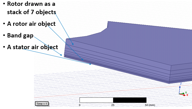
To test various stacking models with pseudo bodies involves recreating the model with different thicknesses and remaking the entire initial mesh. The Tau mesher may not be available for all layer heights. You can achieve comparable results by using skin depth based refinement by reverting to the initial mesh, changing settings and applying mesh operations. The following figure shows a cut-plane image of the interior of a model that uses skin-depth based refinement and layers of elements. The Skin Depth is the total depth of all layers combined. Layered elements apply to the selected faces of solid bodies. The elements are stretched parallel to face, and are compressed in the normal direction.
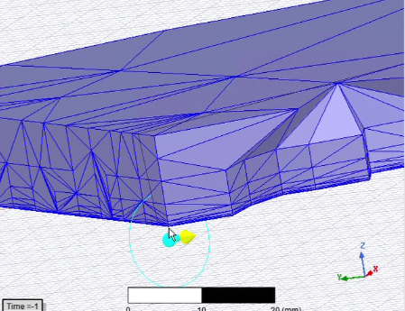
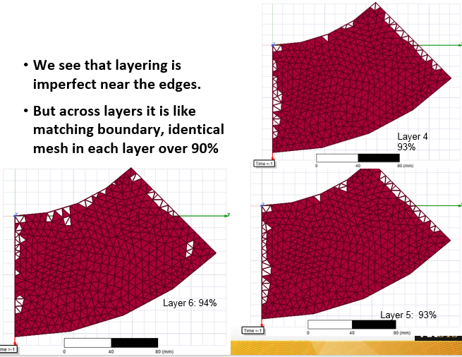
While in some places the edges have imperfect layering, the interior is very good. You can also view the results layer by layer by using the Model Analysis dialog.
The layered skin depth mesh operation provides a tool toward finding a good solution. You can try different settings to improve results toward a good solution. For instance, for this example, these different settings were tried. For comparison, a model built with seven layers required 85K tets.
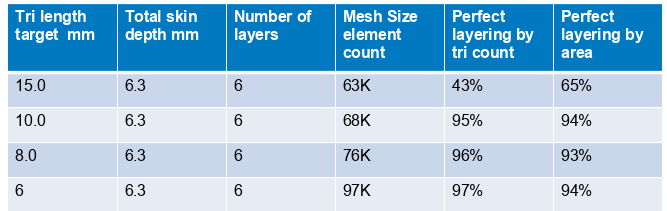
The goal is not to have perfect layering, but to have a good solution that is much easier to achieve.
To use Skin Depth-Based Refinement:
- Select the faces you want to be refined.
Note:
It is possible to select a body and convert it to selecting all faces of the body. The user can use this method to select all faces and toggle a few faces out of selection. Selecting the whole body might select very large regions for refinement and increase the element count a lot.
- Click
The Skin Depth Based Refinement dialog box appears.
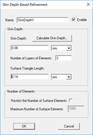
- To calculate the skin depth based on the object's material permeability and conductivity and the frequency at which the mesh will be refined, click Calculate Skin Depth.
The Calculate Skin Depth dialog box appears with values based on the selected object's material properties and the solution setup frequency.
Accept or edit these values. When you click OK the solver calculates the skin depth and enters its value in the Skin Depth text box. You can accept the calculated values or provide your own.
- In the Number of Layers of Elements text box, type the number of layers to add perpendicular to the object's surface. The skin depth is the total depth of all layers combined.
The solver will add an equivalent number of mesh points to each layer. For example, if HFSS added 10 points to satisfy the Surface Triangle Length, it will add 10 points to each layer.
- Optionally, provide the maximum edge length of the surface mesh in the Surface Triangle Length text box. The default value is set to 20% of the maximum edge lengths of the bounding boxes of each selected face.
The solver will refine the surface triangle mesh (the faces of the tetrahedra touching the surface) until their edge lengths are less than or equal to the specified value.
- By default, the Restrict Number of Surface Elements setting is unchecked. This allows the mesher to use symmetry more effectively. If you Restrict the number of surface elements, this may affect symmetry but can be used to protect against runaway refinement in specific cases. To restrict the number of elements added during refinement on the faces uncheck the box to enable the field for Maximum Number of Surface Elements. With the box unchecked, the field, unavailable, the number in the box provides an estimate of mesh growth.
When the mesh is generated, the refinement criteria you specified will be used. This operation will be approximately the same as having slabs of tetrahedra, but it is not guaranteed to prevent tetrahedra from crossing slab interfaces. Caution should be used with this mesh operation, as very thin layers may cause a reduction in mesh quality or unnecessarily cause the generation of a very large mesh. Further regions refined under this operation and its close neighbors do not participate in solution adaptive refinement. This is another reason to use this seeding operation with caution.
You can also specify Initial Mesh Settings to apply to all objects; however, if you apply separate surface approximation mesh operations to specific objects, the object settings take precedence over the general setting.
Visualization for Skin Depth Refinement Mesh Results
You can visualize the mesh to assess results either by using the clip-plane feature on a model with a mesh plot, or by using the Model Analysis dialog box as follows:
- Select the object on which you have generated a meshplot, and click Modeler > Model Analysis > Show Analysis Dialog > View Mesh Feedback.
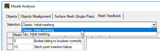
The Model Analysis dialog box appears. If the project has solutions by different solvers, the Selection drop-down menu lets you select which mesh to view.
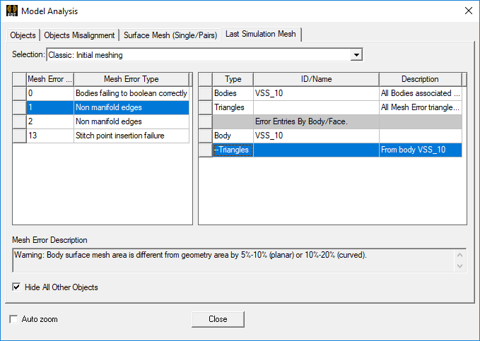
- On the upper left table, under Mesh Error, select 0 through n , where 0 is the selected body, 1 is the layer closest to the face, 2 is the next, up to layer "n" as farthest.
Selecting one of these rows causes a Mesh Error Description to display for the selected layer or body. The message gives the Total Expected count for triangles, as compared with the Success percentage by count and by area.
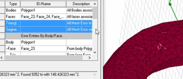
- On the upper right table, select the body, face, or triangle desired, scrolling the list to find any object, face, triangle, or area of interest.
Click Face, to see the selected face.
Select Triangles to see the actual triangles created.
Select Segment to show the triangles attempted.
The following figure shows Triangle and Segment both selected (using Shift+click). Visually, the unfilled triangles represent places where the triangle is not on the desired layer. However the mesh is still very good and supports an accurate solution.
- Check boxes allow you to Hide All Other Objects checked by default, and Auto zoom to selection, unchecked by default.