
Mesh Feedback Tab
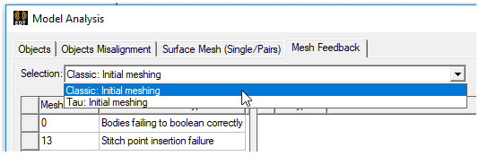
The tables in this panel list model errors as viewed by the mesher. If the project has solutions by different solvers, the Selection drop down lets you select which to view.
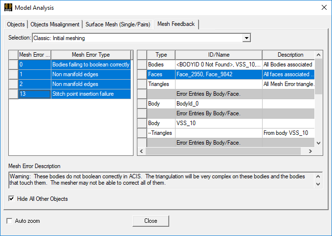
The left side table has columns for Mesh Error Serial ID and Error Type.
- Mesh Error Serial ID – the 0 item is the body with which the subsequently listed entries are associated.
- Mesh Error Type – this column gives the category of error that caused the mesh failure, for example, Non-Manifold Edge, or Point Insertion Failure.
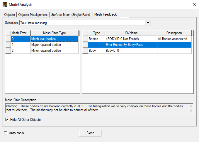
The display in the table on the right side of the Model Analysis window depends on your selections from the left hand table. When you select a row in errors panel (the left panel as shown in above figure), all the faces are selected (second row in right panel) and if you enable Auto Zoom, the view fits to the errors:
- Type – whether the error applies to Bodies, Faces, or Triangles. If you select a particular error type, the columns for Type, ID/Name and Description are filled in.
- ID/Name – the object name or object ID for the error type.
- Description – the first three rows are for Bodies, Faces, and mesh Triangles. Subsequent rows, are of Error Entities By Body.Face.
The Mesh Error Description field describes error message describing the nature of the selected Mesh Error Serial ID, the implications, and provides a recommended response.
Display options include:
- Hide All Other Objects – hides objects in the Modeler window not associated with the selected Bodies, Faces, or Triangles.
- Auto Zoom to Selection – checking this causes the modeler to automatically zoom to objects or faces corresponding to the selected Mesh Error Serial ID (on the left side table) or the ID/Name (on the right side table).
Use of these selections let you more easily view and respond to the errors. If you enable Auto Zoom, any selection whether it is body(ies), face(s) or error triangle(s) or error segment(s) will fit to view. If all the faces are also selected (second row in right panel), then errors and selected entities will fit to view.
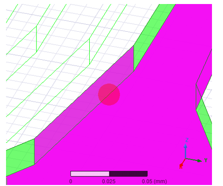
The error shown in the figure above is a contact error between the faces. Focusing only on the errors when an error is selected in right panel, improves visualization of these meshing errors and provides you with precise information in order to take corrective action quickly.
Mesh Error Markers
As shown above the mesh errors are marked by ‘Red Circles’. The following table describes all such markers:
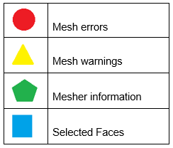
These markers are located at the center of errors or center of faces and their size correspond to the maximum side size of the entity, such as error triangles, error segments or faces. The size of these markers is clamped to a maximum and a minimum size. Additionally they have some transparency. The size and transparency of these markers cannot be changed by the user.
If you select an individual face in the right panel, then the face is marked using a blue square as shown below:
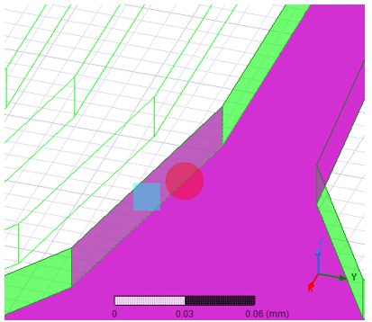
If many individual faces are selected in the right panel, each face is marked by a blue square. In order to find which blue square corresponds to which face in the right panel in the dialog box, click on the blue square. This action selects the corresponding face row in the right panel of the dialog.
Face Selection
When the all faces row or individual face rows are selected, the Modeler selects the face(s). This enables the face related commands in the Modeler window. Also when you select faces this way, it makes the corresponding bodies of the selected faces visible, even when ‘Hide all other objects’ is enabled. This provides some contextual information about the face location with respect to its body.
Multiple Selection of Mesh Errors
You can select multiple rows in the right pane of the Mesh Feedback tab. To view all the meshing errors, select all the rows and enable Auto Zoom, as shown in figures below:
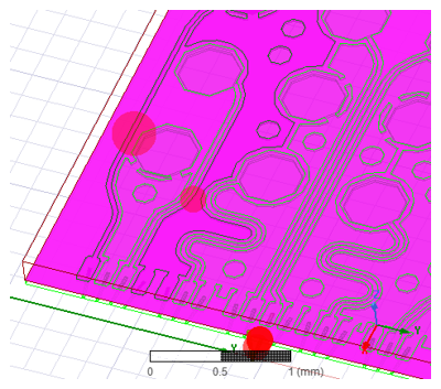
With Auto Zoom enabled, the view fits to all the errors, providing an overview of all the mesh errors, as shown in above figure.
Also, when multiple errors are selected, right panel shows the merged information about all bodies, faces, error triangles etc. And Mesh Error Description text box shows description of all the errors.