
Using Clip Planes
The View > Clipping > Clip Plane command lets you define a clip plane that you can use to interactively make any desired cut-away view of a model. If you use Edit > Copy Image or Modeler > Export> [image format] with the clip plane active, the image shows the clipped plane. When parts of the model are hidden by a clip plane, model selection works as though only the visible parts are present.
To add a clip plane:
- Click View > Clipping > Clip Plane or click the Clipping Planes icon on the View ribbon tab.
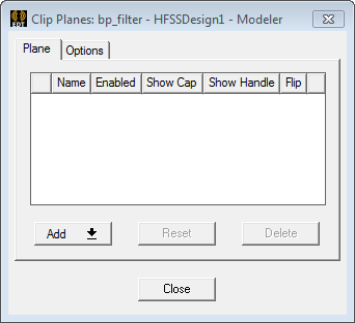
This displays the Clip Plane dialog box with the Plane tab selected.
- The Add button contains a drop-down menu with choices for Specify center, normal, and Use selection.
If you want to use a selection, you must first select a face or an existing cut plane.

- If you first select a face or cut plane, and then click Add > Use Selection, the clip plane is added on that face.
- If you select Add > Specify center, normal, this launches a Measure dialog box and enters a mode for you
to click to define the start location (shown as a triad).
- When you move the cursor, a rectangle represents the clip plane, and a vector the current direction.
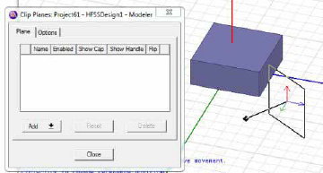
- Click again to set the reference position.
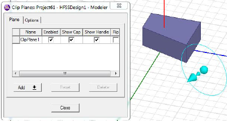
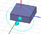
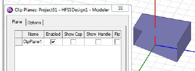
After the second click, the clip plane is active. The handle is visible as a circle with a sphere at the center, and an arrow pointing the normal for the plane. The Clip Planes dialog box shows the clip plane name, that it is enabled, the cap (which is the plane surface), and the handle. Flip selection lets you reverse the direction of the clip plane. If you deselectShow cap and/or show handle, they disappear from the display.
- When you move the cursor, a rectangle represents the clip plane, and a vector the current direction.
- If you first select a face or cut plane, and then click Add > Use Selection, the clip plane is added on that face.
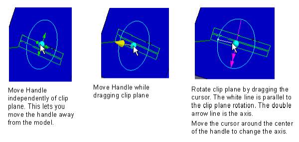
- With Show Handle enabled, you can use
the handle to manipulate the location and orientation of the clip plane.
The handle changes appearance and function relative to the position of
the cursor. Dragging the cursor makes use of the current function.
- The Options tab of the Clip Planes dialog box contains four options:
- Force opaque for the unclipped portion.
- Disable clip plane when drawing a new clip plane.
- Plane handle color
The button shows the current color. Click the button to display a color selection dialog box. Select a default or custom color and click OK.
- Plane handle radius.
This slider lets you resize the radius of the handle to the most convenient size. The radius resizes dynamically. When you close and reopen the modeler window, the last selected size persists.
You can save your choices as new defaults.