


There are three ways to define and solve multiple load steps:
Multiple SOLVE method
Load step file method
Array parameter method.
This method is the most straightforward. It involves issuing the SOLVE command after each load step is defined. The main disadvantage, for interactive use, is that you have to wait for the solution to be completed before defining the next load step. A typical command stream for the multiple SOLVE method is shown below:
/SOLU
...
! Load step 1:
D,...
SF,...
...
SOLVE           ! Solution for load step 1
! Load step 2
F,...
SF,...
...
SOLVE            ! Solution for load step 2
Etc.
The load step file is a convenient method to use when you want to solve problems while you are away from your terminal or PC (for example, overnight). It involves writing each load step to a load step file (via the LSWRITE command) and, with one command, reading in each file and obtaining the solution. See Loading for details about creating load step files.
To solve multiple load steps, issue the LSSOLVE command. The command is actually a macro that reads in the load step files sequentially and initiates the solution for each load step. An example command input for the load step file method is shown here:
/SOLU             ! Enter SOLUTION
...
!  Load Step 1:
D,...                       ! Loads
SF,...
...
NSUBST,...                   ! Load step options
KBC,...
OUTRES,...
OUTPR,...
...
LSWRITE                    ! Writes load step file: Jobname.S01
!  Load Step 2:
D,...                      ! Loads
SF,...
...
NSUBST,...                  ! Load step options
KBC,...
OUTRES,...
OUTPR,...
...
LSWRITE                    ! Writes load step file: Jobname.S02
...
LSSOLVE,1,2         ! Initiates solution for load step files 1 and 2
See the Command Reference for a discussion of the NSUBST, KBC, OUTRES, OUTPR, LSWRITE, and LSSOLVE commands.
This method, mainly intended for transient or nonlinear static (steady-state) analyses, requires knowledge of array parameters and do-loops, which are part of APDL (Ansys Parametric Design Language). See the Ansys Parametric Design Language Guide for information about APDL. The array parameter method involves building tables of load versus time using array parameters and is best explained by the following example.
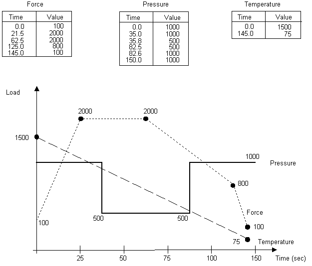
Suppose that you have a set of time-varying loads such as the ones shown above. There are three load functions, so you need to define three array parameters. All three array parameters must be of type TABLE. The force function has five points, so it needs a 5 x 1 array; the pressure function needs a 6 x 1 array; and the temperature function needs a 2 x 1 array. Notice that all three arrays are one-dimensional. The load values are entered in column 1 and the time values are entered in column zero. (The zeroth column and zeroth row, which normally contain index numbers, must be changed and filled with a monotonically increasing set of numbers if you define the array parameter as a TABLE.)
To define the three array parameters, you first need to declare their type and dimensions. To do so, use either of the following:
For example:
*DIM,FORCE,TABLE,5,1
*DIM,PRESSURE,TABLE,6,1
*DIM,TEMP,TABLE,2,1
You can now use either the array parameter editor () or a set of "=" commands to fill these arrays. The latter method is shown below.
FORCE(1,1)=100,2000,2000,800,100  ! Force values in column 1
FORCE(1,0)=0,21.5,50.9,98.7,112   ! Corresponding time values in column 0
FORCE(0,1)=1 ! Zeroth row
PRESSURE(1,1)=1000,1000,500,500,1000,1000
PRESSURE(1,0)=0,35,35.8,74.4,76,112
PRESSURE(0,1)=1
TEMP(1,1)=800,75
TEMP(1,0)=0,112
TEMP(0,1)=1
You have now defined the load histories. To apply these loads and obtain the solution, you need to construct a do-loop (using the commands *DO and *ENDDO) such as the one shown below:
TM_START=1E-6               ! Starting time (must be > 0)
TM_END=112                  ! Ending time of the transient
TM_INCR=1.5                 ! Time increment
*DO,TM,TM_START,TM_END,TM_INCR    ! Do for TM from TM_START to TM_END in
                                  !  steps of TM_INCR
   TIME,TM                  ! Time value
   F,272,FY,FORCE(TM)       ! Time-varying force (at node 272, FY)
   NSEL,...                 ! Select nodes on pressure surface
   SF,ALL,PRES,PRESSURE(TM) ! Time-varying pressure
   NSEL,ALL                 ! Activate all nodes
   NSEL,...                 ! Select nodes for temperature specification
   BF,ALL,TEMP,TEMP(TM)     ! Time-varying temperature
   NSEL,ALL                 ! Activate all nodes
   SOLVE                    ! Initiate solution calculations
*ENDDO
See the Command Reference for discussions of the *DO, TIME, F, NSEL, SF, BF, and *ENDDO commands.
You can change the time increment (TM_INCR parameter) very easily with this method. With other methods, changing the time increment for such complex load histories would be quite cumbersome.