


This section describes the contents and formats of Ansys Fluent legacy case and data files. After discussing the Guidelines and Formatting Conventions in Binary and Formatted Files, the section descriptions are grouped according to function:
Grid Sections : Creating grids for Ansys Fluent.
Data Sections : Importing solutions into another postprocessor.
The legacy case and data files may contain other sections that are intended for internal use only.
The Ansys Fluent legacy case and data files are broken into several sections according to the following guidelines:
Each section is enclosed in parentheses and begins with a decimal integer indicating its type. This integer is different for formatted and binary files (Formatting Conventions in Binary and Formatted Files).
All groups of items are enclosed in parentheses. This makes skipping to ends of (sub)sections and parsing them very easy. It also allows for easy and compatible addition of new items in future releases.
Header information for lists of items is enclosed in separate sets of parentheses preceding the items, and the items are enclosed in their own parentheses.
For formatted files, examples of file sections are given in Grid Sections and Other (Non-Grid) Legacy Case Sections. For binary files, the header indices described in this section
(for example, 10 for the node section) are
preceded by 20 for single-precision binary
data, or by 30 for double-precision binary
data (for example, 2010 or 3010 instead of 10). The end of the binary data
is indicated by End of Binary Section 2010 or End of Binary Section 3010 before the
closing parenthesis of the section.
An example with the binary data represented by periods is as follows:
  (2010 (2 1 2aad 2 3)(
   .
   .
   .
   )
   End of Binary Section 2010)
Grid sections are stored in the legacy case file. A grid file is a subset of a legacy case file, containing only those sections pertaining to the grid. The currently defined grid sections are:
Comment (See Comment)
Header (See Header)
Dimensions (See Dimensions)
Nodes (See Nodes)
Periodic Shadow Faces (See Periodic Shadow Faces)
Cells (See Cells)
Faces (See Faces)
Face Tree (See Face Tree)
Cell Tree (See Cell Tree)
Interface Face Parents (See Interface Face Parents)
The section ID numbers are indicated in both symbolic and numeric forms. The symbolic representations are available as symbols in a Scheme source file (xfile.scm), which is available from Ansys, Inc., or as macros in a C header file (xfile.h), which is located in your installation area.
| Index: | 0 |
| Scheme symbol: |
xf-comment
|
| C macro: |
XF_COMMENT |
| Status: | optional |
Comment sections can appear anywhere in the file (except within other sections) as:
(0 "comment text")
You should precede each long section, or group of related sections, by a comment section explaining what is to follow.
Example:
  (0 "Variables:")
   (37 (
   (relax-mass-flow 1)
   (default-coefficient ())
   (default-method 0)
   ))
| Index: | 1 |
| Scheme symbol: |
xf-header
|
| C macro: |
XF_HEADER |
| Status: | optional |
Header sections can appear anywhere in the file (except within other sections). The following is an example:
(0 "fluent24.2.0 build-id: 0")
The purpose of this section is to identify the program that wrote the file. Although it can appear anywhere, it is one of the first sections in the file. Additional header sections indicate other programs that may have been used in generating the file. It provides a history mechanism showing where the file came from and how it was processed.
| Index: | 2 |
| Scheme symbol: |
xf-dimension
|
| C macro: |
XF_DIMENSION
|
| Status: | optional |
The dimensions of the grid appear as:
(2 ND)
where ND is 2 or 3. This section is
supported as a check that the grid has the appropriate dimension.
| Index: | 10 |
| Scheme symbol: |
xf-node
|
| C macro: |
XF_NODE
|
| Status: | required |
Format:
  (10 (zone-id first-index last-index type ND)(
   x1 y1 z1
   x2 y2 z2
   .
   .
   .
   ))
If
zone-idis zero, this provides the total number of nodes in the grid.first-indexwill then be one,last-indexwill be the total number of nodes in hexadecimal,typeis equal to1,NDis the dimensionality of the grid, and there are no coordinates following (the parentheses for the coordinates are omitted as well).For example:
(10 (0 1 2d5
1 2))
If
zone-idis greater than zero, it indicates the zone to which the nodes belong.first-indexandlast-indexare the indices of the nodes in the zone, in hexadecimal. The values oflast-indexin each zone must be less than or equal to the value in the declaration section. Type is always equal to1.NDis an optional argument that indicates the dimensionality of the node data, whereNDis 2 or 3.If the number of dimensions in the grid is two, as specified by the node header, then only
 and
and  coordinates are present on each
line.
coordinates are present on each
line.
The following is an example of a 2D grid:
  (10 (1 1 2d5 1 2)(
   1.500000e-01 2.500000e-02
   1.625000e-01 1.250000e-02
     .
     .
     .
   1.750000e-01 0.000000e+00
   2.000000e-01 2.500000e-02
   1.875000e-01 1.250000e-02
   ))
Because the grid connectivity is composed of integers representing
pointers (see Cells and Faces), using hexadecimal conserves space
in the file and provides for faster file input and output. The header
indices are in hexadecimal so that they match the indices in the bodies
of the grid connectivity sections. The zone-id and type are also in hexadecimal for consistency.
| Index: | 18 |
| Scheme symbol: |
xf-periodic-face
|
| C macro: |
XF_PERIODIC_FACE |
| Status: | required only for grids with periodic boundaries |
This section indicates the pairings of periodic faces on periodic boundaries. Grids without periodic boundaries do not have sections of this type. The format of the section is as follows:
  (18 (first-index last-index periodic-zone shadow-zone)(
   f00 f01
   f10 f11
   f20 f21
   .
   .
   .
   ))
where
first-index = index of the first periodic face pair in the list |
last-index = index of
the last periodic face pair in the list |
periodic-zone = zone ID of
the periodic face zone |
shadow-zone = zone ID of the corresponding shadow face
zone |
These are in hexadecimal format. The indices in the section
body (f*) refer to the faces on each of the
periodic boundaries (in hexadecimal), the indices being offsets into
the list of faces for the grid.
Note: In this case, first-index and last-index do not refer to face
indices. They refer to indices in the list of periodic pairs.
Example:
  (18 (1 2b a c) (
   12 1f
   13 21
   ad 1c2
   .
   .
   .
   ))
| Index: | 12 |
| Scheme symbol: |
xf-cell
|
| C macro: |
XF_CELL
|
| Status: | required |
The declaration section for cells is similar to that for nodes.
(12 (zone-id first-index last-index type element-type))
Again, zone-id is zero to indicate
that it is a declaration of the total number of cells. If last-index is zero, then there are no cells in the grid.
This is useful when the file contains only a surface mesh to alert Ansys Fluent that
it cannot be used. In a declaration section, the type has a value of zero and the element-type is not present.
For example,
(12 (0 1 3e3 0))
It states that there are 3e3 (hexadecimal) = 995 cells in the grid. This declaration section is required and must precede the regular cell sections.
The element-type in a regular cell
section header indicates the type of cells in the section, as follows:
element-type
| description | nodes/cell | faces/cell |
|---|---|---|---|
| 0 | mixed | ||
| 1 | triangular | 3 | 3 |
| 2 | tetrahedral | 4 | 4 |
| 3 | quadrilateral | 4 | 4 |
| 4 | hexahedral | 8 | 6 |
| 5 | pyramid | 5 | 5 |
| 6 | wedge | 6 | 5 |
| 7 | polyhedral | NN | NF |
where NN and NF will vary, depending on the specific polyhedral cell.
Regular cell sections have no body, but they have a header of
the same format where first-index and last-index indicate the range for the particular zone, type indicates whether the cell zone is an active zone
(solid or fluid), or inactive zone (currently only parent cells resulting
from hanging node adaption). Active zones are represented with type=1, while inactive zones are represented with type=32.
In the earlier versions of Ansys Fluent, a distinction was made between solid and fluid zones. This is now determined by properties (that is, material type).
A type of zero indicates a dead zone
and will be skipped by Ansys Fluent. If a zone is of mixed type (element-type=0), it will have a body that lists the element-type of each cell.
Example:
  (12 (9 1 3d 0 0)(
   1 1 1 3 3 1 1 3 1
   .
   .
   .
   ))
Here, there are 3D (hexadecimal) = 61 cells in cell zone 9, of which the first 3 are triangles, the next 2 are quadrilaterals, and so on.
| Index: | 13 |
| Scheme symbol: |
xf-face
|
| C macro: |
XF_FACE
|
| Status: | required |
The format for face sections is as follows:
(13 (zone-id first-index last-index bc-type face-type))
where
zone-id =
zone ID of the face section |
first-index = index of the first face in
the list |
last-index = index of the last face in the list |
bc-type = ID of the boundary
condition represented by the face section |
face-type = ID of the type(s)
of face(s) in the section |
The current valid boundary condition types are defined in the following table:
bc-type
| description |
| 2 | interior |
| 3 | wall |
| 4 | pressure-inlet, inlet-vent, intake-fan |
| 5 | pressure-outlet, exhaust-fan, outlet-vent |
| 7 | symmetry |
| 8 | periodic-shadow |
| 9 | pressure-far-field |
| 10 | velocity-inlet |
| 12 | periodic |
| 14 | fan, porous-jump, radiator |
| 20 | mass-flow-inlet, mass-flow-outlet |
| 24 | interface |
| 31 | parent (hanging node) |
| 36 | outflow |
| 37 | axis |
The faces resulting from the intersection of non-conformal grids
are placed in a separate face zone, where a factor of 1000 is added
to the bc-type (for example, 1003 is a wall
zone).
The current valid face types are defined in the following table:
face-type
| description | nodes/face |
| 0 | mixed | |
| 2 | linear | 2 |
| 3 | triangular | 3 |
| 4 | quadrilateral | 4 |
| 5 | polygonal | NN |
where NN will vary, depending on the specific polygonal face.
A zone-id of zero indicates a declaration
section, which provides a count of the total number of faces in the
file. Such a section omits the bc-type and
is not followed by a body with further information.
A nonzero zone-id indicates a regular
face section, and will be followed by a body that contains information
about the grid connectivity. Each line of the body will describe one
face and will have the following format:
n0 n1 n2 c0 c1
where,
n* = defining
nodes (vertices) of the face |
c* = adjacent cells |
This is the format for a 3D grid with a triangular face format.
The actual number of nodes depends on the face-type. The order of the cell indices is important, and is determined by
the right-hand rule: if you curl the fingers of your right hand in
the order of the nodes, your thumb will point toward c0.
For 2D grids, n2 is omitted. c1 is determined by the cross product of two vectors,  and
and  . The
. The  vector extends
from
vector extends
from n0 to n1, whereas
the  vector has its origin at
 n0 and points out of the grid plane toward the viewer.
If you extend your right hand along  and curl your
fingers in the direction of the angle between
and curl your
fingers in the direction of the angle between  and
and  , your thumb will point along
  toward
 c1.
If the face zone is of mixed type (face-type= 0) or of polygonal type (face-type= 5),
each line of the section body will begin with a reference to the number
of nodes that make up that particular face, and has the following
format:
x n0 n1 ... nf c0 c1
where,
x = the number
of nodes (vertices) of the face |
nf = the final node of the face |
All cells, faces, and nodes have positive indices. If a face
has a cell only on one side, then either c0 or c1 is zero. For files containing only
a surface mesh, both these values are zero.
For information on face-node connectivity for various cell types in Ansys Fluent, refer to Face-Node Connectivity in Ansys Fluent.
| Index: | 59 |
| Scheme symbol: |
xf-face-tree
|
| C macro: |
XF_FACE_TREE
|
| Status: | only for grids with hanging node adaption |
This section indicates the face hierarchy of the grid containing hanging nodes. The format of the section is as follows:
 (59 (face-id0 face-id1 parent-zone-id child-zone-id)
 (
 number-of-kids kid-id-0 kid-id-1 ... kid-id-n
.
.
.
 ))
where,
face-id0 =
index of the first parent face in the section |
face-id1 = index of the last
parent face in the section |
parent-zone-id = ID of the zone containing
parent faces |
child-zone-id = ID of the zone containing children faces |
number-of-kids = the number
of children of the parent face |
kid-id-n = the face IDs of the children |
These are in hexadecimal format.
| Index: | 58 |
| Scheme symbol: |
xf-cell-tree
|
| C macro: |
XF_CELL_TREE
|
| Status: | only for grids with hanging node adaption |
This section indicates the cell hierarchy of the grid containing hanging nodes. The format of the section is as follows:
 (58 (cell-id0 cell-id1 parent-zone-id child-zone-id)
 (
 number-of-kids kid-id-0 kid-id-1 ... kid-id-n
.
.
.
 ))
where,
cell-id0 =
index of the first parent cell in the section |
cell-id1 = index of the last
parent cell in the section |
parent-zone-id = ID of the zone containing
parent cells |
child-zone-id = ID of the zone containing children cells |
number-of-kids = the number
of children of the parent cell |
kid-id-n = the cell IDs of the children |
These are in hexadecimal format.
| Index: | 61 |
| Scheme symbol: |
xf-face-parents
|
| C macro: |
XF_FACE_PARENTS |
| Status: | only for grids with non-conformal interfaces |
This section indicates the relationship between the intersection faces and original faces. The intersection faces (children) are produced from intersecting two non-conformal surfaces (parents) and are some fraction of the original face. Each child will refer to at least one parent. The format of the section is as follows:
 (61 (face-id0 face-id1)
 (
 parent-id-0 parent-id-1
.
.
.
 ))
where,
|
|
|
|
|
|
These are in hexadecimal format.
If you set up and save a non-conformal mesh in the solution mode of Fluent and then read it using the meshing mode of Fluent, this section will be skipped; consequently, all the information necessary to preserve the non-conformal interface will not be maintained. When you switch to or read the mesh back into the solution mode, you will need to recreate the interface.
Figure 5: Quadrilateral Mesh illustrates a simple quadrilateral mesh with no periodic boundaries or hanging nodes.

The following describes this mesh:
 (0 "Grid:")

 (0 "Dimensions:")
 (2 2)

 (12 (0 1 3 0))
 (13 (0 1 a 0))
 (10 (0 1 8 0 2))

 (12 (7 1 3 1 3))

 (13 (2 1 2 2 2)(
 1 2 1 2 3 4 2 3))

 (13 (3 3 5 3 2)(
 5 1 1 0 1 3 2 0
 3 6 3 0))

 (13 (4 6 8 3 2)(
 7 4 3 0 4 2 2 0
 2 8 1 0))

 (13 (5 9 9 a 2)(
 8 5 1 0))

 (13 (6 a a 24 2)(
 6 7 3 0))

 (10 (1 1 8 1 2)
 (
 1.00000000e+00 0.00000000e+00
 1.00000000e+00 1.00000000e+00
 2.00000000e+00 0.00000000e+00
 2.00000000e+00 1.00000000e+00
 0.00000000e+00 0.00000000e+00
 3.00000000e+00 0.00000000e+00
 3.00000000e+00 1.00000000e+00
 0.00000000e+00 1.00000000e+00))
Figure 6: Quadrilateral Mesh with Periodic Boundaries illustrates a simple quadrilateral mesh with periodic boundaries but no hanging nodes. In this example, bf9 and bf10 are faces on the periodic zones.
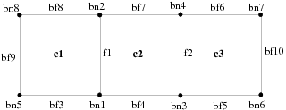
The following describes this mesh:
 (0 "Dimensions:")
 (2 2)

 (0 "Grid:")

 (12 (0 1 3 0))
 (13 (0 1 a 0))
 (10 (0 1 8 0 2))

 (12 (7 1 3 1 3))

 (13 (2 1 2 2 2)(
 1 2 1 2 3 4 2 3))

 (13 (3 3 5 3 2)(
 5 1 1 0 1 3 2 0
 3 6 3 0))

 (13 (4 6 8 3 2)(
 7 4 3 0 4 2 2 0
 2 8 1 0))

 (13 (5 9 9 c 2)(
 8 5 1 0))

 (13 (1 a a 8 2)(
 6 7 3 0))

 (18 (1 1 5 1)(
 9 a))

 (10 (1 1 8 1 2)(
 1.00000000e+00 0.00000000e+00
 1.00000000e+00 1.00000000e+00
 2.00000000e+00 0.00000000e+00
 2.00000000e+00 1.00000000e+00
 0.00000000e+00 0.00000000e+00
 3.00000000e+00 0.00000000e+00
 3.00000000e+00 1.00000000e+00
 0.00000000e+00 1.00000000e+00))
Figure 7: Quadrilateral Mesh with Hanging Nodes illustrates a simple quadrilateral mesh with hanging nodes.
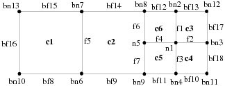
The following describes this mesh:
 (0 "Grid:")

 (0 "Dimensions:")
 (2 2)

 (12 (0 1 7 0))
 (13 (0 1 16 0))
 (10 (0 1 d 0 2))

 (12 (7 1 6 1 3))
 (12 (1 7 7 20 3))

 (58 (7 7 1 7)(
 4 6 5 4 3))

 (13 (2 1 7 2 2)(
 1 2 6 3
 1 3 3 4
 1 4 4 5
 1 5 5 6
 6 7 1 2
 5 8 2 6
 9 5 2 5))

 (13 (3 8 b 3 2)(
 a 6 1 0
 6 9 2 0  4 b 4 0
 9 4 5 0))

 (13 (4 c f 3 2)(
 2 8 6 0
 c 2 3 0
 8 7 2 0
 7 d 1 0))

 (13 (5 10 10 a 2)(
 d a 1 0))

 (13 (6 11 12 24 2)(
 3 c 3 0
 b 3 4 0))

 (13 (b 13 13 1f 2)(
 c 8 7 0))

 (13 (a 14 14 1f 2)(
 b c 7 0))

 (13 (9 15 15 1f 2)(
 9 b 7 0))

 (13 (8 16 16 1f 2)(
 9 8 2 7))

 (59 (13 13 b 4)(
 2 d c))

 (59 (14 14 a 6)(
 2 12 11))

 (59 (15 15 9 3)(
 2 b a))

 (59 (16 16 8 2)(
 2 7 6))

 (10 (1 1 d 1 2)
 (
 2.50000000e+00 5.00000000e-01
 2.50000000e+00 1.00000000e+00
 3.00000000e+00 5.00000000e-01
 2.50000000e+00 0.00000000e+00
 2.00000000e+00 5.00000000e-01
 1.00000000e+00 0.00000000e+00
 1.00000000e+00 1.00000000e+00
 2.00000000e+00 1.00000000e+00
 2.00000000e+00 0.00000000e+00
 0.00000000e+00 0.00000000e+00
 3.00000000e+00 0.00000000e+00
 3.00000000e+00 1.00000000e+00
 0.00000000e+00 1.00000000e+00))
The following sections store boundary conditions, material properties, and solver control settings.
|
Index: |
39 or 45 |
|
Scheme symbol: |
|
|
C macro: |
|
|
Status: |
required |
There is typically one zone section for each zone referenced by the grid. Although some grid zones may not have corresponding zone sections, there cannot be more than one zone section for each zone.
A zone section has the following form:
  (39 (zone-id zone-type zone-name domain-id)(
  (condition1 . value1)
  (condition2 . value2)
  (condition3 . value3)
  .
  .
  .
   ))
Grid generators and other preprocessors need only provide the section header and leave the list of conditions empty, as in
(39 (zone-id zone-type zone-name domain-id)())
The empty parentheses at the end are required. The solver adds
conditions as appropriate, depending on the zone type. When only zone-id, zone-type, zone-name, and domain-id are
specified, the index 45 is preferred for
a zone section. However, the index 39 must
be used if boundary conditions are present, because any and all remaining
information in a section of index 45 after zone-id, zone-type, zone-name, and domain-id will
be ignored.
Here the zone-id is in decimal format. This is in contrast to the use of hexadecimal in the grid
sections.
The zone-type is one of the following:
   axis
   exhaust fan
   fan
   fluid
   inlet vent
   intake fan
   interface
   interior
   mass-flow-inlet
   mass-flow-outlet
   outlet vent
   outflow
   periodic
   porous-jump
   pressure-far-field
   pressure-inlet
   pressure-outlet
   radiator
   shadow
   solid
   symmetry
   velocity-inlet
   wall
The interior, fan, porous-jump, and radiator types can be assigned only to zones of faces inside the domain.
The interior type is used for the faces within
a cell zone; the others are for interior faces that form infinitely
thin surfaces within the domain. Ansys Fluent allows the wall type to be assigned to face zones both on the inside
and on the boundaries of the domain. Some zone types are valid only
for certain types of grid components. For example, cell (element)
zones can be assigned only one of the following types:
  fluid
   solid
All of the other types listed above can be used only for boundary (face) zones.
The zone-name is a user-specified label
for the zone. It must be a valid Scheme symbol [7] and is written without quotes. The rules for a valid zone-name (Scheme symbol) are as follows:
The first character must be a lowercase letter [8] or a special-initial.
Each subsequent character must be a lowercase letter, a special-initial, a digit, or a special-subsequent.
where a special-initial character is one of the following:
! $ % & * / : < = > ? ~ _ ^
and a special-subsequent is one of the following:
. + -
Examples of valid zone names are inlet-port/cold!—,
eggs/easy, and e=m*cˆ2.
Some examples of zone sections produced by grid generators and preprocessors are as follows:
  (39 (1 fluid fuel 1)())
   (39 (8 pressure-inlet pressure-inlet-8 2)())
   (39 (2 wall wing-skin 3)())
   (39 (3 symmetry mid-plane 1)())
The domain-id is an integer that appears
after the zone name, associating the boundary condition with a particular
phase or mixture (sometimes referred to as phase-domains and mixture-domains).
| Index: | 40 |
| Scheme symbol: |
xf-partition
|
| C macro: |
XF_PARTITION
|
| Status: | only for partitioned grids |
This section indicates each cell’s partition. The format of the section is as follows:
 (40 (zone-id first-index last-index partition-count)(
 p1
 p2
 p3
 .
 .
 .
 pn
 ))
where,
p1 = the
partition of the cell whose ID is first-index
|
p2 = the partition of the cell whose ID is first-index  , and so on , and so on |
pn = the partition of the cell whose ID
is last-index
|
partition-count = the total
number of partitions |
Partition IDs must be between 0 and one less than partition-count.
The following sections store iterations, residuals, and data field values.
| Index: | 33 |
| Scheme symbol: |
xf-grid-size
|
| C macro: |
XF_GRID_SIZE
|
| Status: | optional |
This section indicates the number of cells, faces, and nodes in the grid that corresponds to the data in the file. This information is used to check that the data and grid match. The format is
(33 (n-elements n-faces n-nodes))
where the integers are written in decimal.
| Index: | 300 |
| Scheme symbol: |
xf-rf-seg-data
|
| C macro: |
XF_RF_SEG_DATA |
| Status: | required |
This section lists a flow field solution variable for a cell or face zone. The data are stored in the same order as the cells or faces in the legacy case file. Separate sections are written out for each variable for each face or cell zone on which the variable is stored. The format is
  (300 (sub-section-id zone-id size n-time-levels
   n-phases first-id last-id)
   ( data for cell or face with id = first-id
   data-for-cell-or-face with id = first-id+1
   ..
   data-for-cell-or-face with id = last-id
   ))
where sub-section-id is a (decimal)
integer that identifies the variable field (for example, 1 for pressure,
2 for velocity). The complete list of these is available in the header
file (xfile.h), which is located in your
installation area.
where,
|
|
|
|
zone-id matches the ID used in legacy case file.
size is 1 for a scalar, 2 or 3 for a vector, equal to the
number of species for variables defined for each species).
n-time-levels currently are not used.
A sample legacy data file section for the velocity field in a cell zone for a steady-state, single-phase, 2D problem is shown below:
 (300 (2 16 2 0 0 17 100)
 (8.08462024e-01 8.11823010e-02
  8.78750622e-01 3.15509699e-02
  1.06139672e+00 -3.74040119e-02
 ...
  1.33301604e+00 -5.04243895e-02
  6.21703446e-01 -2.46118382e-02
  4.41687912e-01 -1.27046436e-01
  1.03528820e-01 -1.01711005e-01
  ))
The variables that are listed in the legacy data file depend on the models active at the time the file is written. Variables that are required by the solver based on the current model settings but are missing from the legacy data file are set to their default values when the legacy data file is read. Any extra variables that are present in the legacy data file but are not relevant according to current model settings are ignored.
| Index: | 302 |
| Scheme symbol: |
xf-rf-scaled-residuals
|
| C macro: |
XF_RF_SCALED_RESIDUALS
|
| Status: | optional |
This section lists the values of the residuals for a particular data field variable at each iteration:
  (302 (n residual-section-id size domain-id)
  (
  iteration_number unscaled_residual scaling_factor
   .
   .
   .
   ))
where,
|
|
|
|
|
|
|
|
size is 1 for a scalar, 2 or 3 for
a vector, equal to the number of species for variables defined for
each species. The residual-section-id indicates
the equation for which the residual is stored in the section, according
to the C constants defined in a header file (xfile.h) available in your installation area, as noted in Grid Sections.
The equations for which residuals are listed in the legacy data file depend on the models active at the time the file is written. If the residual history is missing from the legacy data file for a currently active equation, it is initialized with zeros.
[7] See Revised (4) Report on the Algorithmic Language Scheme, William Clinger and Jonathan Rees (Editors), 2 November 1991, Section 7.1.1.
[8] The Standard actually only requires that case be insignificant; the Ansys Fluent implementation accomplishes this by converting all uppercase input to lowercase.