Set SBR+ Source Regions
The Set SBR+ Source Regions Command for Hybrid Regions opens a dialog that lets you group source regions for SBR+. Designs containing SBR+ regions will always be set to All One-Way and the Set Coupling menu is replaced by the Set SBR+ Source Regions command. Non-SBR+ regions will serve as sources, and interact with each other through the SBR+ regions. All source regions interact as one-way links to SBR+ and coupling between the source regions are handled by SBR+ using reciprocity theory.
The Set SBR+ Source Regions command appears in the right-click menu of the Hybrid folder at the project tree and at the HFSS>Hybrid menu if an SBR+ Region is assigned. 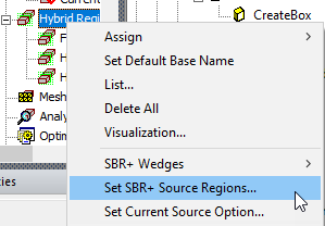
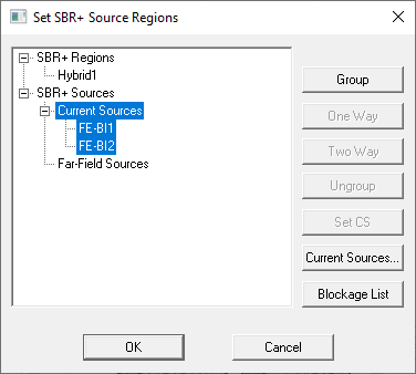
Selecting Set SBR+ Source Regions opens a Set SBR+ Source Regions dialog that lists the SBR+ Regions and the SBR+ Sources in the design. If the design includes an Incident Wave excitation, you see a message that such designs do not support advanced coupling. However, designs with Current Sources and Far Field Sources will be listed in the dialog box.
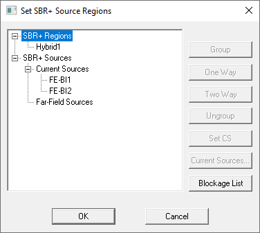
Any Selected regions in this dialog are highlighted in the view window. You can edit groupings (as shown below) but remember that editing groups invalidates existing solutions.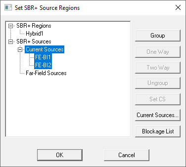
Selecting one or more sources enables the Group button provides a means to designate two-way couplings within a group. The regions so grouped are assigned Two Way coupling. The One Way button is enabled so that you can change their assignment as One Way couplings. The Ungroup button lets you remove coupling groupings.
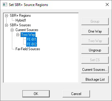
If the design includes Current Sources or Far Fields, these are listed.
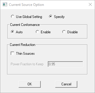
Clicking Current Sources... pops up the Current Source Option dialog that allows you to customize current-source conformance and thinning behavior for the Current Sources region(s) that is currently selected under SBR+ Sources. In this dialog, Use Global Setting is selected by default; in this case, the settings configured in the global-defaults version of the Current Source Option dialog are adopted. If you instead select Specify, then settings for Current Conformance and Current Reduction become enabled and allow configuration that is specific to the Current Sources region(s) selected in the parent dialog. The behaviors and intended usages for these features are further explained in the HFSS Technical Notes for Excitations for SBR+ and Current Conformance and Array Conformance in SBR+.
Current Conformance Settings
For ground-plane backed sources you intend to conform to an SBR+ region, you should place them very near the metallic surface of the SBR+ region to which they will be conformed, and this should be a high-conductivity metal surface or Perfect E boundary. While the conformance algorithm is designed to handle imprecise vertical placement of the source, one should strive to precisely place the source on the intended surface point of the SBR+ region. Also, the conformance algorithm has no ability (or knowledge) to compensate for imprecision in the horizontal placement of the source. Here, “vertical” and “horizontal” mean perpendicular and parallel to the SBR+ region placement surface, respectively.
In the case of sources enclosed by FE-BI boundaries, you should also place a Perfect E infinite ground plane on the FE-BI face nearest the placement surface of the SBR+ region. This ground plane serves two purposes. First, when the source is solved separately and in isolation from the SBR+ region (i.e., in a one-way coupling context), it will experience a grounding environment that best represents the presence of the metallic SBR+ region. Second, this ground plane establishes the reference plane against which current source original heights are measured. When conformance shifts the current sources down toward the SBR+ region placement surface, it will maintain these original heights relative to each underlying point on the SBR+ region placement surface, as explained and illustrated in Current Conformance and Array Conformance in SBR+. Also, when the current sources are generated along the FE-BI faces from their fields during the SBR+ component of the analysis, no current sources will be generated along this ground-plane surface, nor are they required.
The options for Current Conformance are Auto, Enable, and Disable. When set to Disable, conformance is switched off and neither the absolute nor relative positioning of current sources of the SBR+ source are altered.
When Current Conformance is set to Enable, HFSS will attempt to conform the current sources of the ground-plane backed SBR+ source to the nearest surface of the SBR+ region, even in cases where the SBR+ source is far displaced from any SBR+ region. Only select this option when the source defined by current sources is a ground-plane backed antenna that is intended to sit atop and conform to a metallic surface of the SBR+ region.
When Current Conformance is set to Auto, the recommended and default setting, HFSS will automatically determine whether the SBR+ source is a good candidate for conformance. The qualifying criterion is that the source be placed within a small tolerance separation from the nearest SBR+ region surface, this tolerance being determined as one-twentieth (1/20) of the diagonal displacement of source’s bounding box. In addition, in the case of a source enclosed by FE-BI boundaries, if none of these faces is assigned a Perfect E infinite ground plane, Auto conformance will automatically insert one on the FE-BI face nearest the SBR+ region.
Current Reduction Settings
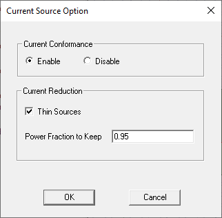
Enabling Thin Sources lets you specify a Power Fraction to Keep between 0 and 1, with lower values implying more thinning, faster solutions, and less accuracy; setting this below 0.9 is not recommended due to the potential excessive accuracy loss. Power Fraction to Keep should not be confused with directly controlling the fraction of current sources to retain; for SBR+ sources with a large number of current sources (e.g., a large FE-BI antenna), substantial thinning far exceeding 10% can be achieved with Power Fraction to Keep set at 0.9 or higher.
Blockage List for SBR+ Source Regions
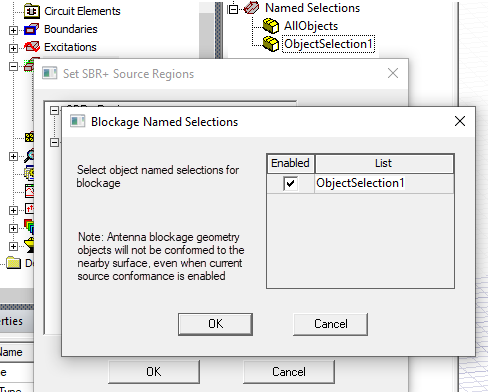
The Blockage List button opens a dialog that lets you view blockage lists. Blockages are allowed when an SBR+ region exist in driven modal and terminal designs. You can easily define an object selection for simulation, and automatically assign blockage structures for each antenna.
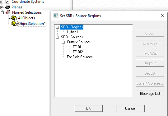
Click the Blockage List button to open a table of available ObjectSelections. Such lists must contain at least one conducting object and have no SBR+ Regions. Enable those lists to treat the objects as blockages.