Current Conformance and Array Conformance in SBR+
Activate Current Conformance to shift the heights of the current sources to better accommodate to the underlying platform structure with which they will be interacting. This capability is primarily intended for antennas requiring a ground plane and that will be placed on a flat or slightly curved metallic section of the platform that will provide this grounding function. It is typically used to make slight adjustments that will improve simulation accuracy and speed. There are a couple of reasons why one should consider using the adjust/conform antenna feature.
- The unadjusted sources may otherwise be too close or possibly even slightly underneath the platform placement surface. In general, placing sources that are conceptually intended to be directly on the surface closer than λ/20 above the surface harms run time with little or no accuracy benefit, as in the case of horizontal magnetic sources representing a slot cut in the placement surface.
- The platform placement surface is slightly curved, the shape of the actual antenna will conform to this curvature, yet the antenna might not exhibit this intended curvature (it's flat)
These situations are common, so the Current Conformance feature is an important capability. When the antenna structure is to be placed directly on the platform, such that it touches the platform, a small source adjustment will often be beneficial.
Example of Current Conformance
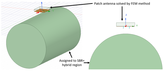
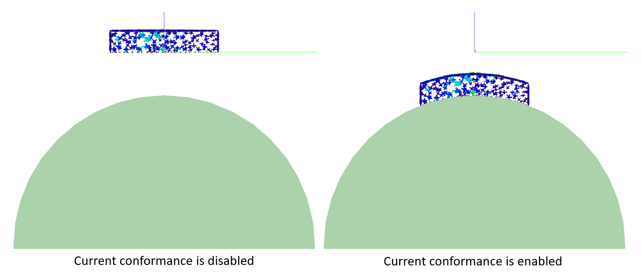
The following driven terminal hybrid design has a patch antenna surrounded by a FEBI region with a Perfect E infinite ground plane, and a PEC cylinder assigned to an SBR+ hybrid region. The fields on the FEBI surface are converted to current sources in the SBR+ simulation. The patch antenna is placed too high relative to the cylinder, as evidenced by the gap between its ground plane and the cylinder. If Current conformance is enabled, the current sources will be shifted parallel to the antenna’s z-axis toward the placement surface, such that their heights above the curved PEC placement surface will match their original heights above the ground plane .
Conformance in SBR+ Parametric Array
Parametric array conformance is processed in two stages, array element conformance, and current conformance if the element antenna is based on current sources.
Array conformance (Conform to Geometry) for Parametric Array
Array conformance may be selected from Conform to Geometry which is found in first page of Create Parametric Array: General dialog. Select Perpendicular to Plane or Along Normal to shift the heights of the elements to better accommodate the underlying platform structure with which they will be interacting. This capability is primarily intended to conform an antenna array that will be placed on a flat or slightly curved metallic section of the platform. See Create and Use Parametric Array in SBR+.
Element Offset specifies the offset as a 3-D Cartesian vector. The elements will be shifted by the fixed offset specified in the local coordinate system of the parametric array. The z-directed offset is also maintained after conformance above the underlying platform structure when Along Normal or Perpendicular to Plane are chosen. Pay attention to sources of element antenna that are not too close to the platform surface. Placing sources directly on the platform surface closer than λ/20 above the surface harms run time with little or no accuracy benefit. Use Element Offset to shift the heights of the elements such that the sources are λ/20 away from platform, in particular, when the element antenna is far-field source. On the other hand, Current Conformance is recommended when element antenna is current source or Near-field link which is explained in later section.
The array conformance is applied after the Element Offset is applied to each array element in antenna local coordinates. There are three options:
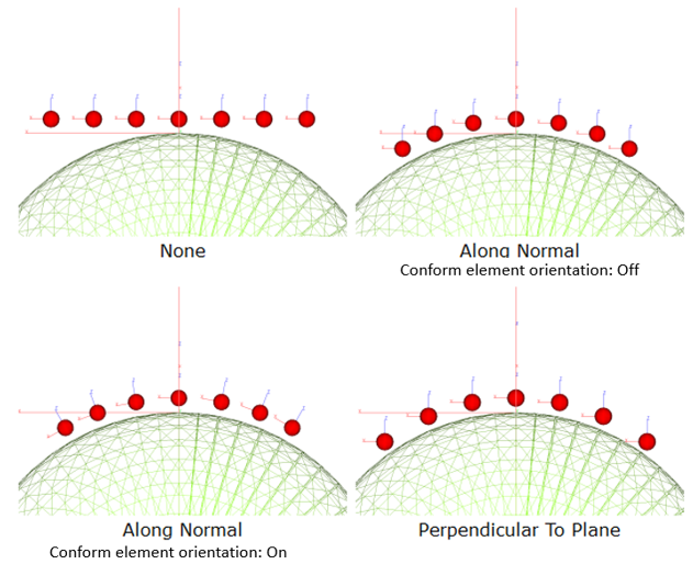
None - No further adjustment after Element Offset is applied.
Along Normal: Element positions are further modified according to the position and perpendicular of the platform surface point Pn closest to each array element. If Conform Element Orientation is also switched on, then the element orientations are similarly modified according to the surface perpendicular at Pn.
Perpendicular to Plane: Element positions are further modified according to the position of the platform surface point Pu directly under each array element.
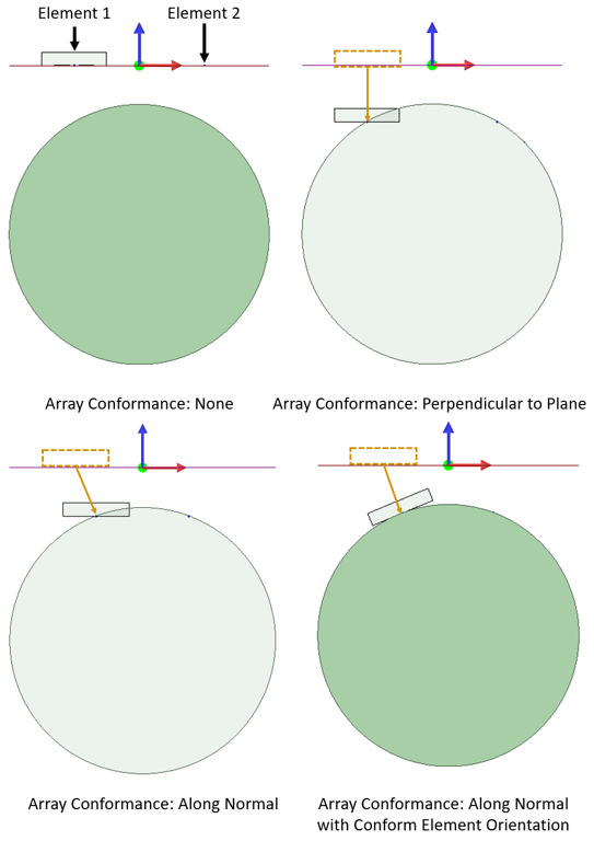
The behavior of these three options is summarized in the illustration below.
The concept behind array conformance is to shift the array element positions so that their height with respect to the array platform on the XY plane is maintained with respect to the SBR CAD platform placement surface. If the platform placement surface is uniformly flat over the extents of the array elements, the elements will be shifted downward to maintain their heights above flat platform surface. If the platform curves away, then the elements will be shifted downward to maintain their heights above the actual curved surface.
One intended use of array conformance is to simplify the modeling task for antennas conforming to the platform surface. Many antennas are not engineered with a particular platform in mind, and their shape is fixed independent of the shape of the placement surface. However, there are applications requiring the antenna to be shaped according to the intended placement surface. For example, this occurs with conformal arrays placed on a fuselage, wing, or some other curved surface.
In these situations, one would ideally capture this curvature in the geometry definition of the array antenna. However, it may not be convenient to do so, as it entails greater effort in developing the model.
The difference between Array Conformance Along Normal and Perpendicular to Plane is the determination of the surface points Pn and Pu relative to which the array elements are repositioned, and also the direction in which these adjustments are applied.
If Array Conformance is Along Normal, then Pn is the surface point nearest the nth array element (after application of Element Offset). The array element is then repositioned at distance h from Pn along the surface perpendicular at that point.
If Conform Element Orientation is switched on (True), then each array element is also rotated to maintain the same orientation relative to the surface tangent plane at each Pn as it had relative to the Reference XY-Plane of the array coordinate. Specifically, if the rotation matrix R would rotate the Reference Plane to the tangent plane at Pn, then the same rotation matrix R is applied to the orientation of the nth array element. It is only available when Conform to Geometry is set to Along Normal.
If Array conformance is Perpendicular to Plane, the surface point Pu is determined by extending a line from each array element (after application of Element Offset) toward the Reference XY-Plane and perpendicular to the same. The first platform surface point intersecting this line is designated as the surface point Pu "under" the array element. The array element is then repositioned along this line to maintain the same distance relative to Pu as its original height h. For this adjustment option, the array elements are never re-oriented; only their positions are shifted.
An example of two element linear array of a patch antenna is shown below. Each element is assigned the same FEBI box source. The first of these two elements is indicated by the element-positioned FEBI box. The second element is depicted as a simple point, but it is important to understand that it also has the same FEBI box centered on it during simulation. In general, with Parametric Array rendering in Desktop, the FEBI box is only drawn for the first element of a parametric ray. This is done to reduce clutter in the visualization and keep the focus on the arrangement of array elements.

When the parametric array is conformed with Array Conformance “None”, all elements are located on XY-plane of the antenna coordinate. On the other hand, when Along Normal or Perpendicular to Plane are selected, elements and element antennas are moved toward the underlying platform structure. Also, when Along Normal and Conform Element Orientation are selected, elements are rotated such that the rotated to maintain the same orientation relative to the surface tangent plane as it had relative to the Reference XY-Plane of the array coordinate.
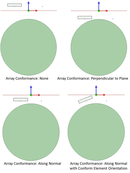
Elements of the array might intersect the placement surface after array conformance. One way to avoid this problem, is to adjust the element offset Z used as the height of the elements above the underlying platform structure. However, this should only be done if it makes physical sense given the actual array being simulated. The alternative resolution, and often the superior one, is to use Current Conformance, which is explained in next section.
Current Conformance for Parametric Array
In addition to Array conformance, Current Conformance is recommended for Parametric Arrays whose elements are parametric antennas with current sources or Near-Field linked antenna.
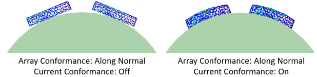
In previous example, Array Conformance Perpendicular to Plane without offset resulted in array elements intersecting the underlying platform structure. When current conformance is off, some current sources intersect the platform structure or end up under the platform structure. When current conformance is enabled, the element current sources are conformed to the platform structure.
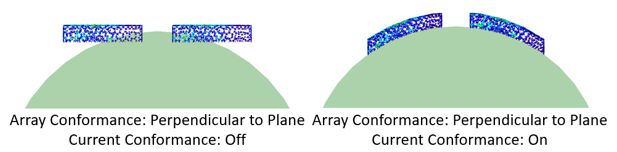
In general, it is recommended to enable current conformance, even in cases where no intersection occurs between the array elements and the platform. This feature helps in detecting if any current source results in being positioned below the platform after conformance, in which case the simulation is aborted with an error message.