To draw an element from the palette in the diagram, select the element in the palette and click the diagram at the position where you want the newly created element to appear.
Note that it is not necessary to use the type concept in medini analyze models--it is possible to work only on the instance level. However, using the type/instance concept eases reuse and increases consistency. For more information about the type/instance concept, see SysML Blocks: Facilitating the type concept.
You can choose the following elements with type character from the palette:
Element type this type denotes a modular unit which describes the structure of system elements. It may have an internal structure and provide ports for communication with other element types. An element type is used to serve as a template (type) to describe a set of instances. The instances of element types are elements. Element type is a generic type, that may appear in more specialized versions that are listed in the following:
System type - this special element type denotes a top level element of the architecture (system or "item" as of ISO 26262)
Component type - this special element type denotes a component.
Interface type - this special element type denotes an interface.
Controller type - this special element type denotes a controller.
Actuator type - this special element type denotes an actuator.
Sensor type - this special element type denotes a sensor.
Hardware part type - this special element type denotes a hardware part.
Software unit type - this special element type denotes a software unit.
Characteristic type - this type denotes a special characteristic of the design.
You can choose the following elements with instance character from the palette. The category of an element, as shown in the Properties dialog, is defined by its type.
Element - an element denotes a system component that is not further specialized in the System/Function Model. You can use it for any kind of element you have in mind. Elements may provide ports as interaction points and may have an internal structure. Element is a generic concept and the following concepts are specializations of element.
System - this special element denotes a top level element of the architecture (system or "item" as of ISO 26262)
Component - this special element denotes a component
Interface - this special element denotes an interface
Controller - this special element denotes a controller
Actuator - this special element denotes an actuator
Sensor - this special element denotes a sensor
Hardware part - this special element denotes a hardware part
Software unit - this special element denotes a software unite
Characteristic - this element denotes a special characteristic of the design
Activity - this element denotes a behavior of an element expressed using a SysML activities/actions flow. For details see SysML Activities and Actions.
Furthermore, there are some elements on the palette that can be applied to instances as well as to types which are used for connections:
Port - a port is an identifiable interaction point of an element to communicate with other elements. A port shows its name and type in the format <name>:<type>. Arrows visualize whether ports send or receive data. To modify these values use the corresponding form editor (see Editing Properties of Model Elements) or the properties view (see Property View for elements).
Connector - a connector is used to denote a communication path between elements. A connector can either connect two elements directly or connect them using the ports of one or both elements.
Dependency - any other dependency between two elements.
The section "Functions" is dedicated to graphical modeling of high-level and technical system functionality and behavior:
Function: a function of the system (high-level or technical)
Requires and Uses: two dependencies between functions and/or other elements
For more details on function modeling, see Functions in the diagram.
After creating an element on the diagram you have to give it a name. All elements--with the exception of connections--also appear as subentries of the model in the Model Browser. Elements are visualized on the diagram using standard diagram elements (rectangular boxes with the icon that characterizes the element and the element name in the header).
Ansys medini analyze supports the specification of structured elements, which are elements which contain other elements. To specify a structured element, select an element from the palette and click onto or into the element you want to contain it. The new element is now embedded in that other element. Add internal connections as required. If you move the containing element, its contained elements are all moved with it. You can also add existing elements to a container or remove elements from a container using drag and drop.
A different approach to specify the internal structure is to use a separate diagram. To add such a diagram, select the entry > from the context menu of any element in the Model Browser or in the graphical editor. The new diagram is added as a subentry to the selected element in the Model Browser and opened automatically. You can now add elements of the internal structure using the graphical editor or by using drag and drop for existing elements from the main diagram. It is also possible to drag and drop ports of the container element from the Model Browser to an internal structure diagram to connect contained elements with them.
The embedding of elements is always visualized in the tree structure of the system/function model in the Model Browser, regardless whether they are embedded directly or whether a separate diagram has been used. If an element is substructured using a separate diagram, this is also visualized by a small diagram icon in the lower right corner of the container element.
Large system/function models can be specified using multiple diagrams where each diagram shows some part of the complete model. Either choose > from the context menu of the top-node of the system/function model in the Model Browser or "Create child diagram" from the context menu of the model's diagram icon in the Model Browser. In addition you can also create a copy of an already existing diagram by selecting "Copy Diagram" from the context menu of the diagram node in the Model Browser.
Double-click the icon for the newly-created diagram to open it in the editor. You may now add new elements to that diagram using the palette or add existing elements by drag & drop from the Model Browser.
Note as each diagram is only a view on the full system/function model, elements of the model may occur on different diagrams. Structural changes, renaming or modification of element details on one diagram will always be reflected on all diagrams containing the concerned element.
Diagrams are part of the hierarchical structure of the model elements. That means, only model elements that are on the same structural level can be visualized/created on a diagram. Elements that are contained in such model elements may be visualized, if the containing element is visualized as well. That means, you may not drag such a contained element by itself onto a diagram - always drag the container element and drop it on the diagram!
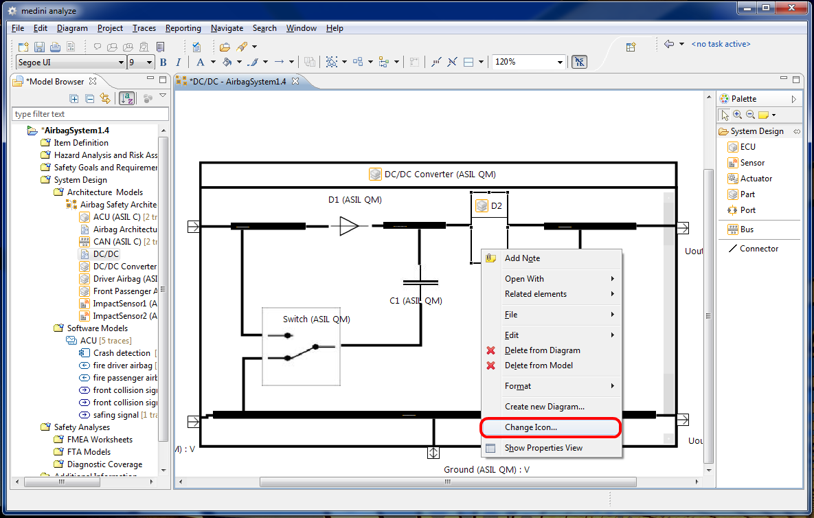
The figures of model elements that appear on diagrams can be changed:
Select an element on a diagram and use the context menu entry Change Icon
In the following dialog, an image file can be chosen. This image is then used within the original box of the element on the diagram.
If you want to remove an icon, you can do the following:
Select the element on the diagram
Select "Delete Icon" from the context menu
Note that if an icon is defined for a type, all of its instances share the icon. That means, that after the creation of the instance it has the same icon as the type. If the icon is deleted or changed at the type, all instances are updated with the new icon on all diagramns where the element is shown.
It is allowed to override the icon of a type at an instance of the type. This is done as usual using the "Change Icon..." action at the instance definition. After the deletion of such an icon at the instance, the icon of the type (if defined) is used again.
Example
The following screenshot shows how some part figures have been replaced by specific images: