


VM-LSDYNA-SOLVE-061
VM-LSDYNA-SOLVE-061
Transient Response of a Ball Impacting a Flexible Surface
Overview
| Reference: | Thomson, W.T (1979). Vibration Theory and Applications. Prentice-Hall, Inc., p.100, Example 4.6-1. |
| Analysis Type(s): | Explicit Dynamics Analysis |
| Element Type(s): | Mass Element, 2D Shell Element |
| Input Files: | Link to Input Files Download Page |
Test Case
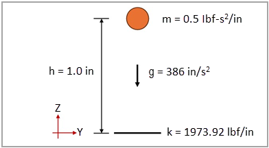
This test case models a rigid ball of mass (m = 0.5 lbf-s2/in) dropped from a height (h = 1 in) onto a flexible surface of stiffness (k = 1973.92 lbf/in). Acceleration due to gravity is considered in the rigid ball. The objective is to validate the time, displacement, velocity, and kinetic energy of the ball at the moment of the impact and the maximum displacement. Figure 198 illustrates the domain dimensions and boundary conditions.
This problem is also presented in test case VM65 in the Mechanical APDL Verification Manual.
The following table lists the material and geometric properties of the test case using the British unit system.
| Material Properties | Geometric Properties | Loading |
|---|---|---|
|
Mass of rigid ball m = 0.5 lbf-s2/in Stiffness constant of flexible surface k = 1973.92 lbf/in |
Initial height h = 1.0 in |
Acceleration due to gravity: g = 386 in/s2 |
Analysis Assumptions
The time  that it takes for a stationary mass to fall from a height h can be calculated:

where  is the acceleration due to gravity. Considering the fall time
 , the velocity and kinetic energy at the moment of the impact can be
calculated
, the velocity and kinetic energy at the moment of the impact can be
calculated


where  is the rigid mass. Therefore, the rigid mass impacts the flexible surface at
0.071982 s with a velocity of -27.785 in/s and a kinetic energy of
193.00 lbf-in. After the impact, the motion of the mass can be described
as:
is the rigid mass. Therefore, the rigid mass impacts the flexible surface at
0.071982 s with a velocity of -27.785 in/s and a kinetic energy of
193.00 lbf-in. After the impact, the motion of the mass can be described
as:

where  is the natural angular frequency of the system.
The time  that it takes for the stationary mass to reach the maximum displacement can be obtained by deriving the equation for
  and solving it for
  :
:

Therefore, the rigid mass experiences a maximum displacement of -1.5507 in at 0.10044 s. In LS-DYNA, the stiffness of the surface is modeled using the contact algorithm. For the penalty formulation, the scale factor for sliding interface penalties (SLSFAC) can be used to impose the contact stiffness:

where
 is the bulk modulus of the material is the bulk modulus of the material |
 is the area of the shell element is the area of the shell element |
 is the diagonal of the shell element is the diagonal of the shell element |
For the current test case, the scale factor for sliding interface penalties (SLSFAC) should be 2.7915 ·10-4 to impose a contact stiffness of 1973.92 lbf/in.
Modeling Notes
Figure 199: Model setup in LS-DYNA of the 3D dynamics analysis of a ball impacting a flexible structure
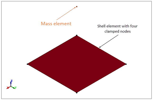
One part is defined to represent the flexible wall that is meshed with a 2D shell element. One mass element of 0.5 lbf-s2/in is defined using *ELEMENT_MASS for a node located 1.0 in away from the center of the wall element. The flexible wall uses a linear elastic material card (*MAT_ELASTIC) with typical steel properties. The motion is fully constrained for the four nodes of the shell element using *BOUNDARY_SPC_SET. Gravity load is defined using *LOAD_BODY_Z with a negative acceleration of 386 in/s2.
The stiffness of the flexible wall is defined through the contact algorithm. The contact between the mass and the shell elements is initialized by *CONTACT_NODES_TO_SURFACE. The scale factor for sliding interface penalties (SLSFAC=2.7915E-04) is specified using *CONTROL_CONTACT to obtain the desired stiffness. A termination time of 0.11 s is defined using *CONTROL_TERMINATION.
Results Comparison
The displacement profile of the rigid mass is shown in Figure 200. The file post.cfile lists the commands used in LS-PrePost to obtain the displacement and velocity plots of the mass.
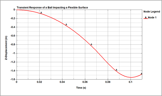
The following table compares LS-DYNA results to theoretical calculations of the time, displacement, velocity, and kinetic energy of the ball at the moment of the impact as well as the maximum displacement. The excellent agreement validates the LS-DYNA model.
| Result | Target | LS-DYNA | Error (%) | |
| At Impact | Time (s) | 0.071982 | 0.071998 | 0.02% |
| Z-Displacement (in) | -1.0000 | -1.0005 | 0.05% | |
| Z-Velocity (in/s) | -27.785 | -27.791 | 0.02% | |
| Kinetic Energy (lbf-in) | 193.00 | 193.10 | 0.05% | |
| At Maximum Displacement | Time (s) | 0.10044 | 0.10000 | -0.44% |
| Z-Displacement (in) | -1.5507 | -1.5505 | -0.01% | |