


VM-LSDYNA-SOLVE-060
VM-LSDYNA-SOLVE-060
Seismic Response of a Simply Supported Beam
Overview
| Reference: | Biggs, J.M (1964). Introduction to Structural Dynamics. McGraw-Hill, p.262, article 6.4. |
| Analysis Type(s): | Implicit Modal, Harmonic Analysis |
| Element Type(s): | 1D Beam Elements |
| Input Files: | Link to Input Files Download Page |
Test Case
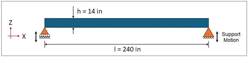
This test case models a simply-supported beam with both supports subjected to vertical motion. The motion is defined in terms of a seismic displacement response-spectrum, with frequencies varying from 0.1 to 10.0 Hz and a displacement amplitude of 0.44 in. The beam has a length of 240 in and cross-section properties defined below. The objective is to validate the natural frequency, the maximum deflection, and the maximum bending stress of the beam. Figure 196 illustrates the domain dimensions and boundary conditions.
This problem is also presented in test case VM70 in the Mechanical APDL Verification Manual.
Figure 196: Schematic of the test case, including domain geometry, main dimensions, and boundary conditions
| Material Properties | Geometric Properties | Loading |
|---|---|---|
|
Young's modulus E = 3 ⋅ 107 psi Poisson's ratio ν = 0.3 Density ρ = 7.30 ⋅ 10-4 lbf-s2/in4 |
Beam length l = 240 in Beam height h = 14 in Moment of inertia I = 333.3333 in4 Cross-sectional area A = 273.9726 in2 |
Base displacement spectrum with an amplitude (umax) of 0.44 in and frequencies (f) from 0.1 to 10.0 Hz |
Analysis Assumptions and Modeling Notes
The natural frequency of a simply supported beam can be calculated as:
 | (48) |
where
 is the beam length is the beam length |
 is the Young's modulus is the Young's modulus |
 is the moment of inertia is the moment of inertia |
and  is the mass per unit length is the mass per unit length |
The mass per unit length  is calculated as the product of the material density ρ and the
cross-sectional area A. The natural frequency of the current system is
6.09793 Hz. For a simply-supported beam subjected to support motion, the
maximum deflection
is calculated as the product of the material density ρ and the
cross-sectional area A. The natural frequency of the current system is
6.09793 Hz. For a simply-supported beam subjected to support motion, the
maximum deflection  can be calculated as:
 | (49) |
where  is the maximum displacement of the beam support. For the current test case,
the maximum deflection is 0.56023 in. The maximum bending stress can be
calculated as:
is the maximum displacement of the beam support. For the current test case,
the maximum deflection is 0.56023 in. The maximum bending stress can be
calculated as:
 | (50) |
where  is the maximum moment of the beam and
  is the maximum cross-section dimension measured from the neutral axis (h/2
in the current problem). Therefore, the maximum bending stress is 2.01586 ⋅
104 psi.
is the maximum cross-section dimension measured from the neutral axis (h/2
in the current problem). Therefore, the maximum bending stress is 2.01586 ⋅
104 psi.
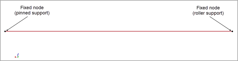
One part is defined to represent the beam, being meshed with 1D beam elements. These elements use Belytschko-Schwer resultant beam formulation (ELFORM=2) with cross-sectional properties defined from the table above. The beam elements use a linear elastic material card (*MAT_ELASTIC) with material properties defined from the table above. The keyword *BOUNDARY_SPC_NODE is used to define the pinned-roller conditions of both end nodes, while *BOUNDARY_SPC_NODE_SET is used to constrain the motion of all nodes in XZ plane. The keywords *CONTROL_IMPLICIT_GENERAL (IMFLAG=1) and *CONTROL_IMPLICIT_EIGENVALUE (NEIG=1) are used to activate the implicit eigenvalue analysis with one eigenvalue to be extracted. The keywords *FREQUENCY_DOMAIN_RESPONSE_SPECTRUM and *DATABASE_FREQUENCY_BINARY_D3SPCM are used to activate and create the binary output file for the response spectrum analysis generated due to the excitation of the base.
Results Comparison
The visualization of the fundamental mode can be performed by reading the d3eigv file, generated for the modal analysis. The relative displacement of the nodes can be observed in the d3spcm file, generated for the response spectrum analysis. To quantify the error between the theoretical and LS-DYNA results, the natural frequency, maximum deflection, and maximum bending stress of the simply supported beam are calculated with their relative errors and shown in the following table. Since beam stresses cannot be directly obtained with the current element formulation, the maximum bending moment was obtained and used to calculate the maximum bending stress. This comparison verifies the agreement between the natural frequencies, maximum deflections, and maximum bending stresses.
| Results | Target | LS-DYNA Solver | Error (%) |
|---|---|---|---|
| Natural Frequency (Hz) | 6.09793 | 6.09503 | -0.05% |
| Maximum Deflection (in) | 0.56023 | 0.56006 | -0.03% |
| Maximum Bending Stress (psi) | 2.01586 ⋅ 104 | 2.01361 ⋅ 104 | -0.11% |