


VM-LSDYNA-SOLVE-059
VM-LSDYNA-SOLVE-059
Portal Frame Under Symmetric Loading
Overview
| Reference: | Hoff, N.J. (1956). The Analysis of Structures. John Wiley and Sons, Inc., p.115-118. |
| Analysis Type(s): | Implicit Static Structural Analysis |
| Element Type(s): | 1D Beam Elements |
| Input Files: | Link to Input Files Download Page |
Test Case
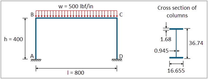
This test case models a rectangular frame subjected to a uniform distributed load  of 500 lbf/in across the span BC, illustrated in Figure 194. The columns AB and CD are
identical with a length of 400 in and a moment of inertia
of 500 lbf/in across the span BC, illustrated in Figure 194. The columns AB and CD are
identical with a length of 400 in and a moment of inertia  . The horizontal span has a length of 800 in and a moment of
inertia five times the moment of inertia of the columns (
. The horizontal span has a length of 800 in and a moment of
inertia five times the moment of inertia of the columns ( ). All members of the frame have an I-Beam cross-section with the columns
following W36x300 dimensions. The ends A and D of the columns are clamped. The objective is to
validate the rotation of the rigid connection B and maximum bending moment of the
frame.
). All members of the frame have an I-Beam cross-section with the columns
following W36x300 dimensions. The ends A and D of the columns are clamped. The objective is to
validate the rotation of the rigid connection B and maximum bending moment of the
frame.
This problem is also presented in test case VM217 in the Mechanical APDL Verification Manual.
The following table lists the main parameters of the test case, which uses the following system of units: length in in, time in s, mass in lbf-s²/in, force in lbf, and pressure in psi.
| Material Properties | Geometric Properties | Loading |
|---|---|---|
|
Young’s modulus
Poisson’s ratio
Density
|
Span length
Column height
|
Distributed load
|


Analysis Assumptions and Modeling Notes
As shown in Figure 194, the
dimensions of a W36x300 I-Beam cross-section used in the columns are  = 16.655 in,
  = 36.74 in,
  = 0.945 in, and
  = 1.68 in. This cross-section has a moment of inertia
 of 2.01389 ⋅
104 in4. For the
horizontal span, the I-Beam cross-section dimensions are scaled by a factor of 1.49535 for its
moment of inertia to be five times the moment of inertia of the columns.
of 2.01389 ⋅
104 in4. For the
horizontal span, the I-Beam cross-section dimensions are scaled by a factor of 1.49535 for its
moment of inertia to be five times the moment of inertia of the columns.
For a portal frame subjected to a uniform distributed load  across its span with
  and
and  , the rotation of the rigid connection B can be calculated as:
 | (46) |
where
 is the column height is the column height |
and  is the Young’s modulus is the Young’s modulus |
The rotation of the rigid connection is 1.96168 ⋅ 10-3 for the current test case. The maximum bending moment of the structure occurs in the middle of its span and can be calculated as:
 | (47) |
For the current test case, the maximum bending moment of the bar is 2.81481 ⋅ 107 lbf-in.
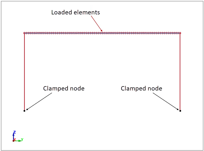
Two parts are defined to represent the horizontal span and the columns of the portal frame, being meshed with 1D beam elements. These elements use Belytschko-Schwer full cross-section integration (ELFORM=4) with an arbitrary cross-section type (QR/IRID=-1, CST=2). The I-Shape cross-section integration rule is defined using *INTEGRATION_BEAM (ICST=1, K=2) with the specific dimensions of each part. Both parts use a linear elastic material card (*MAT_ELASTIC) with properties listed in the table above. The keyword *BOUNDARY_SPC_NODE is used to define the clamped condition of both end nodes, while *BOUNDARY_SPC_NODE_SET is used to constrain the motion of all nodes in YZ plane. The distributed load is prescribed to all beams of the horizontal spam using *LOAD_BEAM_SET. The keywords *CONTROL_IMPLICIT_DYNAMICS (IMASS=0) and *CONTROL_IMPLICIT_GENERAL (IMFLAG=1) are used to activate the implicit static structural analysis.
Figure 195: Model setup in LS-DYNA of the 2D structural analysis of portal frame under symmetric loading
Results Comparison
The visualization of the final configuration of the portal frame subjected to the distributed load can be performed by reading the d3plot file. The maximum bending moment (S-direction beam moment) is located in the middle of the horizontal span, as predicted in theory. To quantify the error between the theoretical and LS-DYNA results, the rotation of the rigid connection and the maximum bending moment of the frame are calculated with their relative errors and shown in the following table. This comparison verifies the agreement between the rotations and bending moments.
| Results | Target | LS-DYNA Solver | Error (%) |
|---|---|---|---|
| Rotation of rigid connection B | 1.96168 ⋅ 10-3 | 1.99587 ⋅ 10-3 | 1.74 |
| Maximum bending moment (lbf-in) | 2.81481 ⋅ 107 | 2.82207 ⋅ 107 | 0.26 |