


VM-LSDYNA-SOLVE-058
VM-LSDYNA-SOLVE-058
Buckling of a Bar with Hinged Ends (Beam Elements)
Overview
| Reference: | Timoshenko, S. (1956). Strength of Material, Part II, Elementary Theory and Problems (3rd edition). D. Van Nostrand Company Inc., p.148, article 29. |
| Analysis Type(s): | Implicit Buckling Analysis |
| Element Type(s): | 1D Beam Elements |
| Input Files: | Link to Input Files Download Page |
Test Case
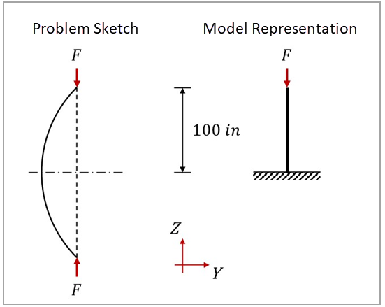
This test case models the elastic buckling of a long, uniform bar with hinged ends subjected to axial loading. The bar has a length of 200 in and a square cross-section with sides of 0.5 in. The objective is to validate the critical buckling load of the bar. Due to symmetry, each half of the bar is equivalent to a free-clamped buckling scenario. For this reason, only the upper half of the bar is modeled in the LS-DYNA application. Figure 192 illustrates the domain dimensions and boundary conditions.
This problem is also presented in test case VM127 in the Mechanical APDL Verification Manual.
Figure 192: Schematic of the test case, including domain geometry, main dimensions, and boundary conditions
The following table lists the main parameters of the test case, which uses the following system of units: length in in, time in s, mass in lbf-s2/in, force in lbf, and pressure in psi.
| Material Properties | Geometric Properties | Loading |
|---|---|---|
|
Young’s modulus E = 3 ⋅ 107 psi Poisson's ratio ν = 0.3 Density ρ = 7.28 ⋅ 10-4 lbf-s2/in4 |
Bar length l = 200 in Cross-section sides w = 0.5 in |
Compression force F = 1 lbf |
Analysis Assumptions and Modeling Notes
The critical load  for a long, uniform bar with hinged ends can be calculated as:
 | (45) |
Where  is the Young's modulus,
  is the moment of inertia, and
  is the bar length. The moment of inertia of a square is
w4/12, where w is the square side. For the current test case, the
critical load of the bar is 38.5531 lbf.
is the bar length. The moment of inertia of a square is
w4/12, where w is the square side. For the current test case, the
critical load of the bar is 38.5531 lbf.
Figure 193: Model setup in the LS-DYNA application of the 1D buckling analysis of a bar with hinged ends
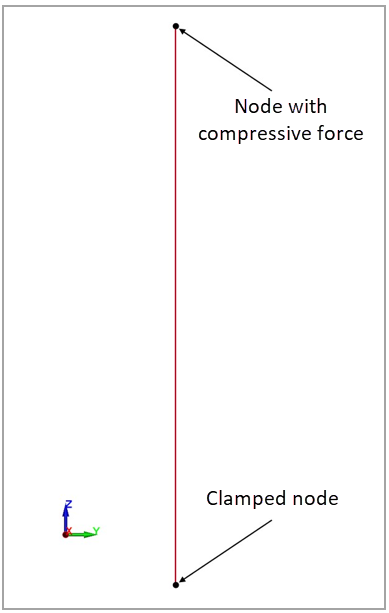
One part is defined to represent the bar, being meshed with 1D beam elements. These elements have length of 10 in and use a linear elastic material card (*MAT_ELASTIC) with properties listed in the table above. The keyword *BOUNDARY_SPC_NODE is used to define the motion constraint of the bottom end node. The compressive force is prescribed to the top end node using *LOAD_NODE_POINT. The keywords *CONTROL_IMPLICIT_GENERAL (IMFLAG=1), *CONTROL_IMPLICIT_BUCKLE (NMODE=1), and *CONTROL_IMPLICIT_EIGENVALUE (NEIG=0) are used to activate the implicit eigenvalue, buckling analysis with one buckling mode to be computed.
Results Comparison
The visualization of the first buckling mode can be performed by reading the d3eigv file generated for the modal analysis. To quantify the error between the theoretical and LS-DYNA results, the critical buckling load of the bar and its relative error is calculated and shown in the following table. The critical load from the LS-DYNA solver is obtained by multiplying the load factor (eigenvalue) printed in the eigout file by the compressive load F. This comparison verifies the agreement between the critical loads.
| Results | Target | LS-DYNA Solver | Error (%) |
|---|---|---|---|
Critical load  (lbf) (lbf) | 38.5531 | 38.7117 | 0.41% |