


VM-LSDYNA-SOLVE-055
VM-LSDYNA-SOLVE-055
Transient Response of a Mass-Spring-Damper System
Overview
| Reference: | Thomson, W. T. (1971). Vibration theory and applications. (3rd impression). Prentice-Hall, Inc., page 41, example 2.2-1. |
| Analysis Type(s): | Explicit Dynamics Analysis |
| Element Type(s): | 1D Discrete Elements, Mass Elements |
| Input Files: | Link to Input Files Download Page |
Test Case
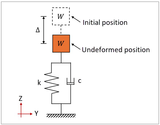
This test case models a mass-spring-damper system, which is displaced by a distance Δ when released. The mass weighs 10 lbf, and the spring stiffness is 30 lbf/in. The following four damping ratios are tested: 0.0, 0.2, 1.0, and 2.0. The objective is to validate the displacement profile of each system. The spring length is arbitrarily defined as 2.0 in, and the initial displacement is 1 in. Figure 185 illustrates the domain dimensions and boundary conditions.
This problem is also presented in test case VM71 in the Mechanical APDL Verification Manual.
The following table lists the main parameters of the test case, which uses the following system of units: length in in, time in s, mass in lbf-s²/in, force in lbf, and pressure in psi.
| Material Properties | Geometric Properties | Loading |
|---|---|---|
|
Weight of concentrated mass: W = 10 lbf Stiffness constant: k = 30 lbf/in Damping ratios: ξ = 0.0, 0.2, 1.0, and 2.0 |
Spring length: l = 2.0 in |
Initial displacement: Δ = 1 in |
Analysis Assumptions and Modeling Notes
The damping ratio  specifies the damping of the system (c) in terms of the critical damping
(cc). When the system damping is lower than critical (
specifies the damping of the system (c) in terms of the critical damping
(cc). When the system damping is lower than critical ( > 1.0), the general solution of a mass-spring-damper system is calculated
as:
> 1.0), the general solution of a mass-spring-damper system is calculated
as:
 | (34) |
where  is the angular natural frequency of the system (
 ), and
  and
and  are intergration constants. For a damping greater than critical
(> 1.0), the motion equation of the system is calculated as:
are intergration constants. For a damping greater than critical
(> 1.0), the motion equation of the system is calculated as:
 | (35) |
where  and
and  are integration constants. For the critical damping (> 1.0), the motion of the system is described as:
 | (36) |
where  is the integration constant. To implement damper elements in the model, the
damping coefficients
is the integration constant. To implement damper elements in the model, the
damping coefficients  need to be calculated:
 | (37) |
The weight of the concentrated mass (W = 10.0 lbf) can be divided by acceleration due to gravity (g = 386 in/s2) to obtain the mass (m = 0.025907 lbf-s2/in). For the current test case, the damping coefficients are 3.52636, 1.76318, 0.35264, and 0 lbf-s/in.
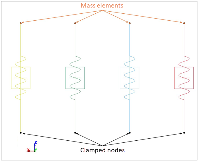
Eight parts are defined to represent four springs and four dampers, being meshed with 1D discrete elements. Each pair of spring and damper elements is connected by the same end nodes. The spring elements use an elastic spring material card (*MAT_SPRING_ELASTIC) with stiffness of 30 lbf/in. The damper elements use a viscous damper material card (*MAT_VISCOUS_DAMPER) with the calculated damping coefficients. A mass element of 0.025907 lbf-s2/in is defined for the top node of each spring-damper pair using *ELEMENT_MASS. The bottom nodes have their translational and rotational constraints defined with *BOUNDARY_SPC_NODE.
Dynamic relaxation is used to implement the initial displacement Δ of the system as a preload step (*CONTROL_DYNAMIC_RELAXATION with IDRFLG=1). The top nodes have their initial translation in Z-direction defined with *BOUNDARY_PRESCRIBED_MOTION_NODE, using a ramped curve that is only activated in the dynamic relaxation phase (prior to the dynamic analysis). A termination time of 0.1 ms is defined with *CONTROL_TERMINATION for the dynamic analysis phase.
Results Comparison
The displacement profile of each mass-spring-damper system is shown in Figure 187. Note that all curves start at 1.0 in due to the preload analysis performed using dynamic relaxation.
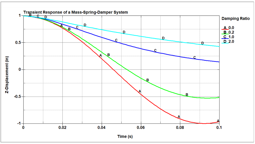
To quantify the error between the theoretical and LS-DYNA results, the displacement at t = 0.09 s and the relative error of each mass-spring-damper system are calculated and shown in the following table. This comparison verifies the agreement between the displacements.
The results table below shows the comparison between the displacement value at 0.09 s of the mass-spring-damper systems calculated using theory and the LS-DYNA model.
| Results | Target | LS-DYNASolver | Error (%) |
|---|---|---|---|
| Displacement (in) for damping ratio of 2.0 | 0.47420 | 0.47179 | -0.51% |
| Displacement (in) for damping ratio of 1.0 | 0.18998 | 0.18904 | -0.50% |
| Displacement (in) for damping ratio of 0.2 | -0.52110 | -0.51849 | -0.50% |
| Displacement (in) for damping ratio of 0.0 | -0.99689 | -0.99189 | -0.50% |