


VM-LSDYNA-SOLVE-052
VM-LSDYNA-SOLVE-052
Natural Frequencies of a Two-Mass-Spring System
Overview
| Reference: | Thomson, W. T. (1971). Vibration theory and applications (3rd impression). Prentice-Hall, p.163, example 6.2-2. |
| Analysis Type(s): | Implicit Vibration Analysis |
| Element Type(s): | 1D Discrete Elements, Mass Elements |
| Input Files: | Link to Input Files Download Page |
Test Case
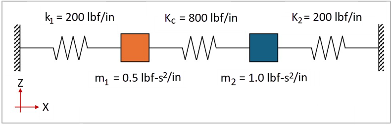
This test case models a system composed of two masses and three springs, illustrated in Figure 179. The first mass is 0.5 lb-s2/in, and the second mass is 1.0 lb-s2/in. The first two springs have a stiffness of 200 lbf/in, while the central spring has a stiffness of 800 lbf/in. The objective is to validate the two normal modes and natural frequencies of the system. The spring lengths are arbitrarily defined as 1.0 in.
This problem is also presented in test case VM89 in the Mechanical APDL Verification Manual.
The following table lists the material and geometric properties of the test case.
| Material Properties | Geometric Properties |
|---|---|
|
Stiffness constant of spring 1 (k1) = 200 lbf/in Stiffness constant of spring 2 (k2) = 200 lbf/in Stiffness constant of central spring (kc) = 800 lbf/in Mass 1 (m1) = 0.5 lbf-s2/in Mass 2 (m2) = 1.0 lbf-s2/in | Spring lengths (l) = 1 in |
Analysis Assumptions and Modeling Notes
The characteristic equation for a two-mass-spring system can be described as:
 | (26) |
where
 is the natural angular frequency for mode is the natural angular frequency for mode  |
 , ,  , and , and  are the stiffness constants of the springs 1, 2, and central are the stiffness constants of the springs 1, 2, and central |
 and and  are the concentrated masses 1 and 2 are the concentrated masses 1 and 2 |
For the parameters specified in the table above, the two natural angular frequencies of
the system are  = 16.25 rad/s and
  = 52.31 rad/s. Therefore, the natural frequencies of the
system are
= 52.31 rad/s. Therefore, the natural frequencies of the
system are  = 2.5860 Hz and
  = 8.3249 Hz.
Using the natural angular frequencies of the system, the following equation can be used to
calculate the amplitude ratios describing the normal modes  :
:
 | (27) |
Therefore,  = 0.92 and
  = -2.17.
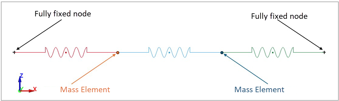
Three parts are defined to represent the springs, being meshed with 1D discrete elements. These elements have a length of 1 in and use a spring material card (*MAT_SPRING_ELASTIC). A mass element is defined in each node connecting two consecutive spring elements using *ELEMENT_MASS. The keyword *BOUNDARY_SPC_NODE is used to define the motion constraints of both end nodes. The keywords *CONTROL_IMPLICIT_GENERAL (IMFLAG=1), *CONTROL_IMPLICIT_DYNAMICS (IMASS=0), and *CONTROL_IMPLICIT_EIGENVALUE (NEIG=2) are used to activate the implicit eigenvalue static analysis with two eigenvalues to be extracted.
Results Comparison
The visualization of the two modes can be performed by reading the d3eigv file, generated for the modal analysis. To quantify the error between the theoretical and LS-DYNA results, the amplitude ratios and natural frequencies of the two-mass-spring system and their relative errors are calculated and shown in the following table. This comparison verifies the agreement between the natural frequencies and amplitude ratios.
| Results | Target | LS-DYNA Solver | Error (%) |
|---|---|---|---|
|
Natural Frequency |
2.5860 |
2.5814 |
-0.18% |
|
Natural Frequency |
8.3249 |
8.3263 |
0.02% |
|
Amplitude ratio |
0.9200 |
0.9212 |
0.13% |
|
Amplitude ratio |
-2.1700 |
-2.1712 |
0.05% |

