


VM-LSDYNA-SOLVE-048
VM-LSDYNA-SOLVE-048
Transverse Natural Frequencies of a Cantilever Tube
Overview
| Reference: | Blevins, R. D. (1979). Formulas for natural frequency and mode shape. Van Nostrand Reinhold. |
| Analysis Type(s): | Implicit Vibration Analysis |
| Element Type(s): | 3D Hexahedral Elements |
| Input Files: | Link to Input Files Download Page |
Test Case
The finite element simulation presented in this test case models the vibration of a cantilever tube. The simulation results show the first three transverse natural frequencies of the structure. These values are validated against theoretical values for an identical scenario to verify the accuracy of the LS-DYNA solver.
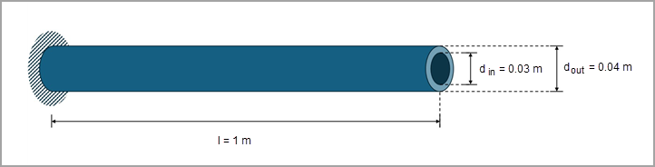
Figure 169 provides a schematic of the test case, showing the tube, clamped at one end, with an outer diameter of 0.04 m, an inner diameter of 0.03 m, and a length of 1 m.
The table that follows shows the corresponding material and geometric properties. This test case uses the International System of Units: length in m, time in s, mass in kg, force in N, and stress in Pa.
| Material Properties | Geometric Properties |
|---|---|
|
Young's modulus (E) = 2.04 · 1011 Pa Poisson's ratio (ν) = 0.3 Density (ρ) = 8020 kg/m3 |
Tube length (l) = 1 m Tube outer radius (rout) = 0.02 m Tube inner radius (rin) = 0.015 m |
Analysis Assumptions
For a cantilever tube with uniform, linear elastic material, the following formula is used to calculate the transverse natural frequencies ( ).
).
 | (21) |
where
 represents a dimensionless parameter. represents a dimensionless parameter. |
 represents Young's modulus. represents Young's modulus. |
 represents the area moment of inertia around the neutral axis (see Equation 22). represents the area moment of inertia around the neutral axis (see Equation 22). |
 represents the tube length . represents the tube length . |
 represents the tube mass per unit length. represents the tube mass per unit length. |
The parameter is a function of the boundary conditions, and the transverse mode index ( ) represents the number of nodal lines in the tube length.
The area moment of intertia around the neutral axis for an annular disc () is a function of its radii and is calculated using the following formula:
 | (22) |
For the current test case, the area moment of inertia is 8.59 · 10-8 m4 and the mass per unit length is 4.41 kg/m. The dimensionless parameters are as follows for a free-clamped condition:
 = 1.87510407 = 1.87510407 |
 = 4.69409113 = 4.69409113 |
 = 7.85475744 = 7.85475744 |
Therefore, the natural frequencies for the first three transverse modes are as follows:
| First Mode = 35.28 Hz |
| Second Mode = 221.09 Hz |
| Third Mode = 619.05 Hz |
Modeling Notes
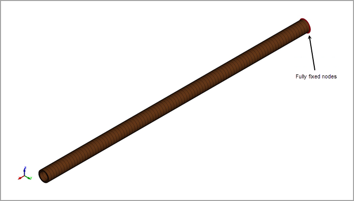
The cantilever tube is defined as a single part meshed with 3D hexahedral elements. The elements are 0.01 m in the axial direction, 0.001 m in the radial direction, and 0.0019 m to 0.0024 m in the angular direction. They use a constant stress solid element formulation (*SECTION_SOLID with ELFORM = 1) and an elastic material card (*MAT_ELASTIC) with the material properties outlined above in test case overview.
The nodes corresponding to one end surface are grouped using *SET_NODE_LIST, and the keyword *BOUNDARY_SPC_SET is used to define the motion constraints of this node set (translational and rotational constraint about the three axes).
The keywords *CONTROL_IMPLICIT_GENERAL (IMFLAG=1), *CONTROL_IMPLICIT_DYNAMICS (IMASS=0), and *CONTROL_IMPLICIT_EIGENVALUE (NEIG=6) are used to activate the implicit eigenvalue, static analysis with six eigenvalues to be extracted.
Results Comparison
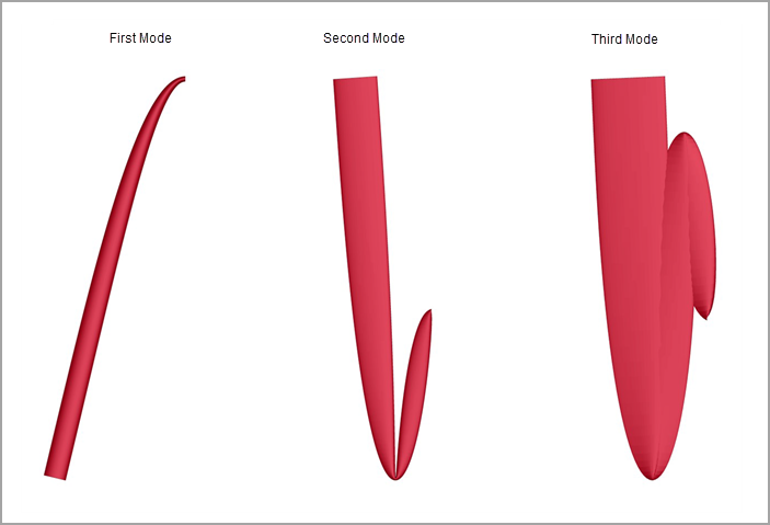
Figure 171 shows the configuration of the cantilever tube for the first three transverse natrual frequencies. This visualization is performed by reading the d3eigv file generated for the modal analysis. Note that there are two orthogonal modes associated with each of the three transverse natural frequencies (totaling six transverse modes) due to the circular cross-section of the beam.
To validate the model and verify the accuracy of the LS-DYNA solver, the first three transverse natrual frequencies of the tube resulting from the simulation were compared to the theoretical results. This comparison shows excellent agreement between the two results.
| Results | Target | LS-DYNA Solver | Error (%) |
|---|---|---|---|
| First Transverse Natural Frequency (f1), Hz | 35.28 | 35.18 | -0.28 |
| Second Transverse Natural Frequency (f2), Hz | 221.09 | 217.82 | -1.48 |
| Third Transverse Natural Frequency (f3), Hz | 619.05 | 598.79 | -3.27 |