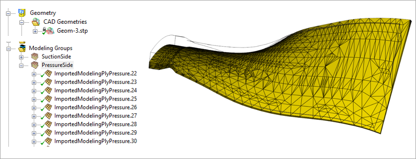
In the T‑joint example, standard modeling plies based on a reference surface are used to define the layup. In this example, the layup is created using Imported Plies (see Figure 4.82: Layup Modeled using Imported Plies), where the ply surfaces are imported directly from the CAD geometry. This approach is useful when a layup definition already exists in a CAD tool or when a reference‑surface‑based method cannot achieve the required accuracy.
Imported-Ply Definition
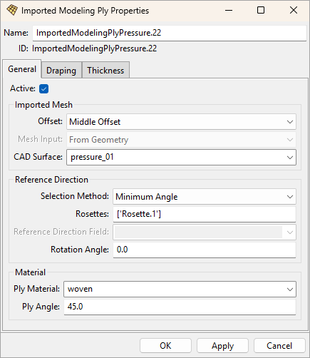
Each Imported Modeling Ply (see Figure 4.83: Imported Modeling Ply Properties) is linked to a CAD surface that represents the mid‑plane of the ply. A fabric and one or more rosettes are then assigned to the imported plies to define the material and fiber orientations. The mesh shown on the imported ply is the tessellation of the CAD surface. The surface‑mesh quality is not critical for the structural analysis because it is intersected with the base solid mesh to generate the reinforcing elements.
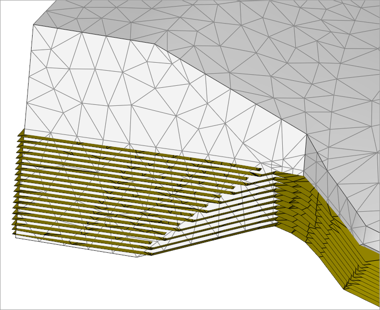
The solid mesh and reinforcing surfaces of the root section are shown in Figure 4.84: Root‑Section Visualization. The visualization illustrates that the solid mesh does not need to follow the ply staggering, and the solid elements do not need to align with the laminate normal. It also shows that imported reinforcing plies (CAD surfaces) can extend beyond the solid mesh; any excess material is removed when the reinforcing elements are intersected with the base solid mesh.
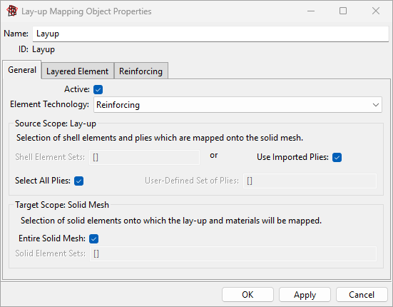
The definition of the Imported Solid Model is straightforward in this example. The entire solid mesh can be combined with all Imported Modeling Plies, so a single Layup Mapping Object is sufficient (see Figure 4.85: Layup Mapping Object Properties).