This option enables mapping orientations from beam elements (the connection between the beam nodes) to shell meshes for use with other composite material models in the LS-DYNA application simulations.
This section covers the following topics:
| SourceFile = STRING | Define the name and, if needed, the path of the source file (usually a *.dynain file). |
| TargetFile = STRING | Define the name and, if needed, the path of the target file. The target file must be an LS-DYNA application mesh. |
| MappingResult = STRING | Define the result file name. The mapping result is written into this newly generated file. |
|
OrientationFile = HISV Nodes | To enable the transfer of orientations, define this flag. It informs the program that the orientation data is stored within the history variables (HISV). Alternatively, orientations can be derived from the element nodes. This method may yield accurate results if the mesh is well-aligned initially. |
| TransformedMeshFile = STRING | Specify the file name where the transformed mesh is written. This option is intended solely for postprocessing of the transformation. For additional details, refer to the Transformation Options section below. |
The following options are available for the source, target, and result file formats:
|
SourceFileFormat = LS-DYNA ESI-PC Nastran HDF5 ESI-HDF5 GCODE ABAQUS STEP CSV | The source file format. The preferred format is LS-DYNA. |
| TargetFileFormat = LS-DYNA | The target file format. The only format available is LS-DYNA. |
| ResultFileFormat = LS-DYNA | The result file format. The only format available is LS-DYNA. |
| NumTargetPids = INT |
Define the number of parts in the target mesh which are considered within the mapping. This option must be followed by TargetPid#i definitions. |
| TargetPid#i = INT | Define as many part IDs as given in NumTargetPids. These parts are considered for the mapping. |
| NumSourcePIDs = INT |
Define the number of parts in the source mesh which are considered within the mapping. This option must be followed by SourcePID#i definitions. |
| SourcePID#i = INT | Define as many part IDs as given in NumSourcePIDs. These parts are considered for the mapping. |
Note: The options above specifically narrow down the scope of the mapping procedure to defined-part IDs. Other parts are ignored on both the source and target meshes.
|
TRANSFORMATION = YES NO | Turns the transformation option on or off. |
|
WriteTransformedMesh = YES NO | Flag to enable output of the transformed mesh for mapping. This enables verifying the success of the transformation. If set to YES, a TransformedMeshFile must be specified (see Input and Output Meshes ). |
There are three available methods for performing mesh transformation:
TRAFO_OPTION is required:
Iterative Closest Point (ICP)
Four-Points-Congruent Sets (4PCS)
TRAFO_OPTION is not required:
User-defined translation and rotation
The 4PCS method must be used with caution, as it is fully automatic and may not accurately transform stress tensors and fiber orientations between different coordinate systems. The ICP algorithm is the recommended approach.
The user-defined translation and rotation options are listed underneath TRAFO_OPTION.
Note: Transformation options are used to transform the source mesh.
|
TRAFO_OPTION = 4PCS ICP | Flag that enables specification of the desired transformation option. |
| NodalPair#i = INT INT | Define nodal pairs to initialize mesh alignment for the ICP algorithm. You may specify up to ten nodal pairs, with a required minimum of three. In each pair, the first integer represents a node ID in the source mesh, and the second corresponds to a node ID in the target mesh. Input values must be space-separated, with each nodal pair provided on a separate line. |
| MAX_NUM_ITER = INT | Maximum number of iterations to be performed by the 4PCS algorithm. |
| GLOBAL_ERR = DOUBLE | Global error measure to accept transformation as best fit 4PCS algorithm. |
| MATCHING_POINT_DIST = DOUBLE |
Maximum distance between points so that they are accepted as matching (4PCS). |
| PERCENTAGE_OF_MATCHING_POINTS = DOUBLE | Percentage of matching points to accept the transformation (4PCS). |
Additionally, a custom sequence of user-defined transformations can be applied. These transformations are executed in the order in which they are specified and multiple transformations may be defined:
|
RotateSRC = DOUBLE;X DOUBLE;Y DOUBLE;Z DOUBLE; DOUBLE DOUBLE DOUBLE | The source mesh rotates by a specified angle (first value, in degrees) around a defined axis. Predefined axes include X, Y, and Z. Alternatively, a custom axis can be specified by providing three space-separated floating-point values following a semicolon (; x y z). |
| MoveSRC = DOUBLE DOUBLE DOUBLE | The source mesh moves along the user-defined vector (x y z). |
| ScaleSRC = DOUBLE | The source mesh scales around the origin using the defined scale factor. |
In addition to the transformation options, there are options to convert the unit systems:
| ChangeUnitSystem = YES/NO | Activates or deactives unit system conversion. |
|
SourceUnitSystem = kg - m - s ton - mm - s kg - mm - ms g - mm - ms lb - in - s | If the unit system conversion is activated, provide information about the source unit system. |
|
TargetUnitSystem = kg - m - s ton - mm - s kg - mm - ms g - mm - ms lb - in - s | If the unit system conversion is activated, provide information about the target unit system. |
|
ALGORITHM = ClosestPoint ElementSizeSearchRadius ConsiderOndulation |
For the ClosestPoint option, values are mapped to the nearest node, integration point, or element center. |
|
Search_Radius = SrcEleLen TarEleLen DOUBLE | Specifies the search radius for the mapping algorithm. By default, SrcEleLen is used, which sets the radius to the average element size of the source mesh. Alternatively, you can use TarEleLen to apply the average element size of the target mesh, or provide a positive DOUBLE value to define a custom radius. |
| Scale_SearchRadius = DOUBLE | Coefficient to scale search buckets in bucket search algorithm. |
|
MapStress = YES NO | Define if stresses have to be transferred or not. |
|
MapStrain = YES NO | Define if strains have to be transferred or not. |
|
MapThickness = YES NO | Define if thicknesses have to be transferred or not. This option requires *ELEMENT_SHELL_THICKNESS cards in the *.dynain file and overwrites the value of TargetThickness. |
| TargetThickness = DOUBLE | Define the thickness in the target shell mesh. |
| NPLANE = INT |
1 - Reduced integrated thick shell elements 4 - Fully integrated thick shell elements This option is formerly known as NumberOfTARInPlaneIPs. |
| NTHICK = INT | Define the number of through-thickness integration points (IPs). Ensure the number of through-thickness IPs refers to the number of fibers being mapped, the number of source shell element stacks, and the number of through-thickness IPs in the source mesh. The number of through thickness IPs can be reduced using the ThroughThicknessAveraging option. See also Figure 4.3: Number of stacks, integration points and fiber IDs for *MAT 249 or Note 1 in the Shell to Shell (500012) mapping option. This option is formerly known as NumberOfTARThroughThicknessIPs. |
| ResinMatID = INT | This option can be set for the ElementSizeSearchRadius or ConsiderOndulation option. Assigns a specific material ID to integration points where no neighboring element is found that assigns a fiber orientation. If no value is given, a default is used to assign a material ID for specific resinuous areas. |
| RovingWidth = DOUBLE | Define roving width that a beam element represents. ClosestPoint option conditions are enhanced according to this coefficient. |
|
IntegrationRule = Gauss Lobatto Autoform Moldflow |
Define the through thickness integration rule of the mapping result. This option directly affects the positions of the through thickness integration points on the target mesh. |
|
Shell_Option = BETA COMPOSITE COMPOSITE LONG |
Define shell output option. There is no default value for this option. Therefore it must be defined. |
| SORT = BUCKET |
Using bucket sort is strongly recommended, as it provides a substantial performance improvement for the search algorithm. |
| REPEAT = YES |
Enable this option to ensure that all elements and integration points receive mapped data. When there is a significant difference in element sizes between the source and target meshes, the default bucket refinement may be insufficient to cover all points, sometimes by design. In such cases, this flag must be set to guarantee complete data coverage. |
Further options for Algorithm=ConsiderOndulation option are:
|
SourcePID = TargetMID TargetPlyID |
Flag for assigning source part ID as target material ID or target ply ID. Shell_Option=COMPOSITE (Long) must be declared. |
Further options for the mapping of fiber orientations from *MAT 249 (*MAT_REINFORCED_THERMOPLASTIC) [20] are:
| TargetMaterialModel = 249 |
Target mesh material model number. If the option is defined, the fiber directions is stored according to IHIS=1 option. Shell_Option=COMPOSITE must be defined to utilize this option in full capacity. More information about the material model can be found in [20]. See Remarks. |
|
ThroughThicknessAveraging = YES NO | Set to YES if orientation averaging is performed through the thickness of the source parts, or if a specific stacking sequence is needed to define the fiber orientation. Use this option where orientations are being transformed and appears in a specific order other than arbitrary orientations through the thickness. If YES, the remaining inputs in this table must be defined. |
| NumberOfFiberBundles = INT | Define how many averaging options are performed. |
| FiberBundle#i: | Counter for fiber bundles. |
| Lay = INT, IP = INT, Fib = INT | Repeat this card as often as necessary for each of the averaging possibilities. Lay refers to the Layer (same numbering as in SourcePid#i) of stacked elements in the source mesh. IP refers to the respective IP in that layer, and Fib to the respective fiber. All values listed here are averaged until the next different input parameter is defined. |
Remark 1
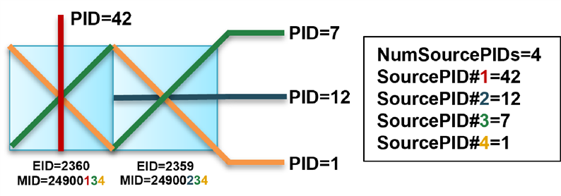
The method in the figure below provides a consistent and reliable way to assign material IDs to *ELEMENT_SHELL_COMPOSITE layers using *MAT 249 as the target material model. The method reduces the number of maximum possibilities by regulating material IDs.
Figure 4.1: Illustration of Method to Assign Individual Composite Layer Integration Point Material IDs in *ELEMENT_SHELL_COMPOSITE Keyword
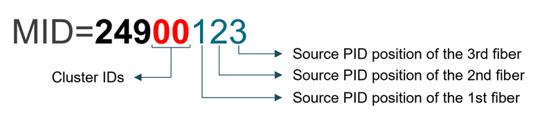
The material ID is limited to eight digits. The initial three digits indicate that the target material model is *MAT 249. The following two digits are for the clustering method. Finally, the last three digits represent fibers, since *MAT 249 supports up to three fibers per integration point (IP). The fiber digits indicate the position of the found beam element PIDs declaration as source part ID in mapping command file. An example is provided in Figure 4.2: Example of Method to Assign Material IDs. If an element has less than three fibers, this method assigns 0 to preserve the eight digit material ID.