


Compatibility issues may arise due to the kernel transition. If you encounter issues, review the following guidance to resolve them. These issues are expected to be progressively addressed in upcoming service packs. If there are concerns about compatibility, consider upgrading to a later version when it is released.
If using the 2025 R1 version is not essential, it may be beneficial to wait for future releases that offer improved compatibility.
Error: The version of the save file is unsupported and cannot be read
This error occurs if you attempt to open legacy files directly in 2025 R1 without saving them in 2024 R2 SP3 first. Legacy files must be saved in 2024 R2 SP3 to include additional data necessary for conversion to Parasolid.
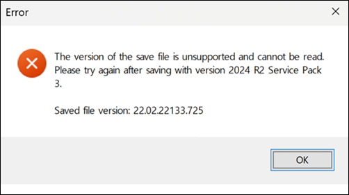
Note: In the Saved file version displayed in the error dialog
above, the first two segments represent the <Major
Version>.<Minor Version>. The major
version corresponds to the last two digits of the release year (for example,
2022 is represented as 22), while the minor version
refers to the release number (for example, R1 or R2). Version
22.02 therefore corresponds to 2022 R2.
If 2025 R1 SP2 and 2024 R2 SP3 are installed on the same system, enabling the Opening files saved from versions prior to 2024 R2 Service Pack 3 Lab feature allows legacy files to be opened directly in 2025 R1 SP2 without manually saving them in 2024 R2 SP3. For detailed instructions, refer to Mandatory Steps to Load Legacy Files, Step 2.
If you try to open legacy files saved in 2024 R2 SP3 without enabling the Legacy ACIS Kernel-Based File Support feature, an error message will appear. To proceed, enable Legacy ACIS Kernel-Based File Support in > , then retry.
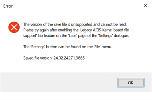
For detailed instructions on loading legacy files in 2025 R1, refer to Mandatory Steps to Load Legacy Files.
Parasolid conversion failure for legacy files
If conversion of legacy files to Parasolid fails, the message
CONVERSION FAILED will appear in the
Conversion tab of the Output window.
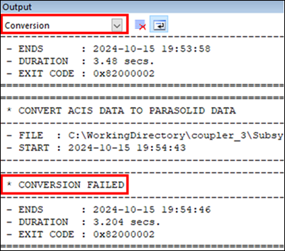
Common reasons for conversion failure include:
Excessive facesets and contact entities: Models with a large number of facesets and contact entities may fail to load. To resolve this, remove contact entities and facesets in 2024 R2 SP3, load the file in 2025 R1, and reconfigure the contact and faceset settings.
Defective CAD geometry: Certain bodies may fail to load due to geometry defects. If a model loads successfully after removing a particular body in 2024 R2 SP3, that body may be defective. Fix the geometry in a CAD tool or use healing options in 2025 R1 after re-importing the CAD, then reconfigure any necessary connectors and contacts.
Absence of 2024 R2 SP3: If 2024 R2 SP3 is not installed, only Hoops Exchange is available as the Conversion Engine, increasing the likelihood of conversion failures. If 2024 R2 SP3 is installed, InterOp will be used as a fallback if Hoops Exchange conversion fails. Install 2024 R2 SP3 and reload the legacy files in 2025 R1 if necessary.
- Updated solution in 2025 R1 SP2
In 2025 R1 SP2, was introduced as the default conversion engine, resolving most conversion failure issues. This engine effectively addresses common problems, such as models with excessive facesets and contact entities or defective geometries. If conversion fails, ensure the engine is active in the settings and retry the conversion.
For detailed instructions on configuring Stride Convert, refer to Mandatory Steps to Load Legacy Files, Step 2.
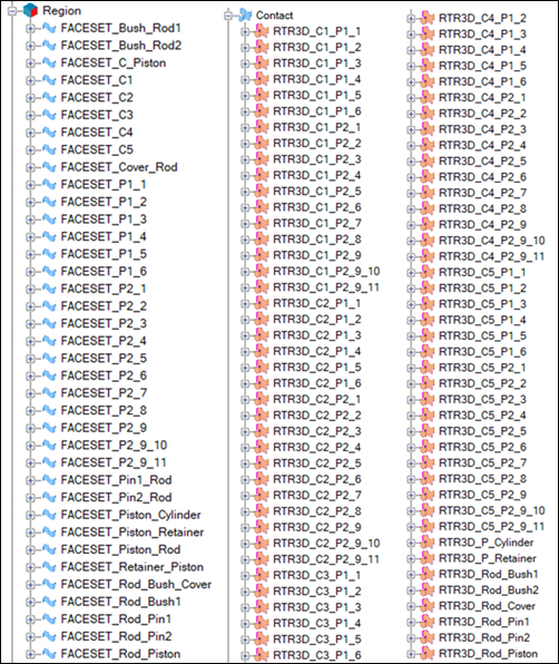
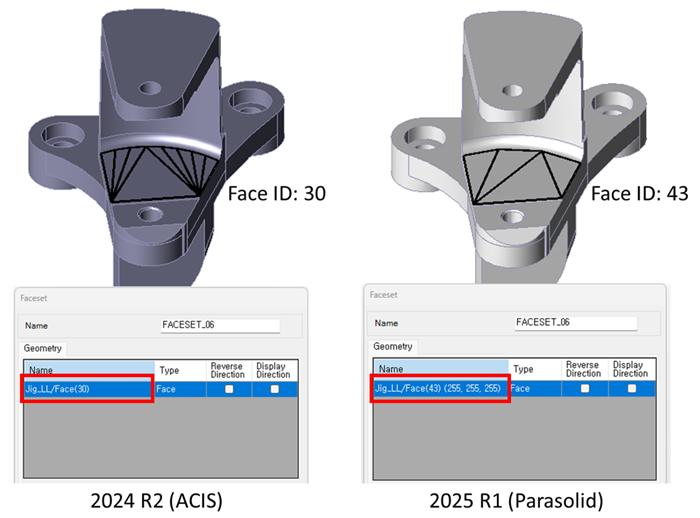
Change in Faceset ID after Parasolid conversion
When legacy files are converted to Parasolid, the IDs of faces or edges in facesets or edgesets may change. This may affect Preprocessor API scripts or journal files that reference specific face or edge IDs, which may cause them to function incorrectly. Update the IDs in the API code or journal files accordingly.
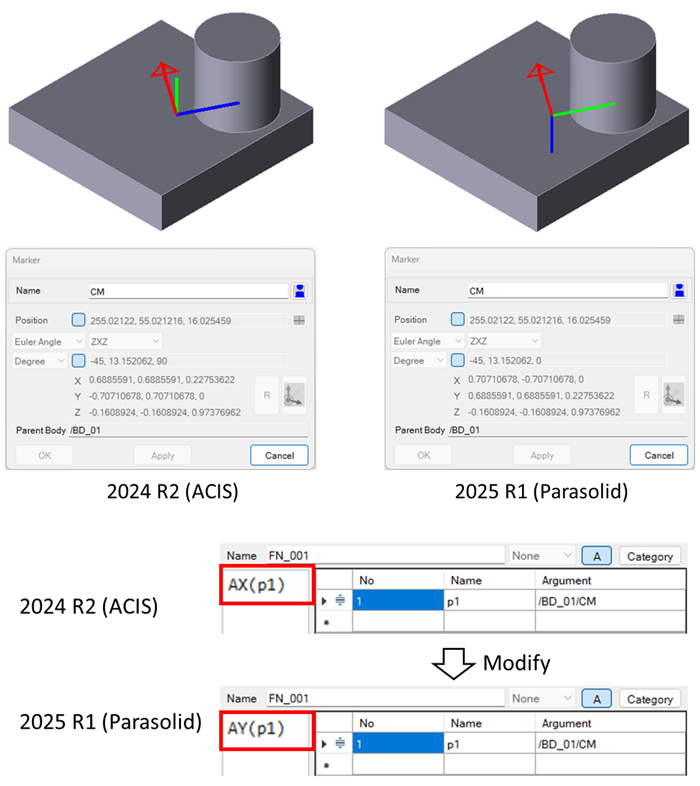
Solution variation due to CM Marker orientation changes
The CM (Center of Mass) Marker orientation in rigid bodies may differ when legacy
files are loaded in 2025 R1 due to kernel transition. If CM Marker orientation is
used in function expressions, as a reference marker in forces, boundary conditions,
or measures, or if CM Marker rotation is monitored in the postprocessor, the
solution may differ from previous versions. Adjust the model to align with the
updated CM Marker orientation. For example, if you previously measured
AX(p1) in a function expression, adjust it to
AY(p1) in 2025 R1 as shown in the figure below.
Variation in contact results
Changes in faceting rules due to the kernel transition may alter the number and arrangement of facets in Facesets, potentially affecting contact results. To achieve results similar to those in legacy files, adjust the faceting parameters as closely as possible to the original settings. Verify that all faces in facesets match those in the legacy files.
Variation in EasyFlex body results
Due to changes in faceting rules, facet shapes within EasyFlex bodies may differ, which can affect results. Additionally, output facet shapes for EasyFlex bodies may vary, impacting overall report results. Adjust the faceting options for the Facesets and Geometry for Output to closely match those in the legacy files for consistent results.
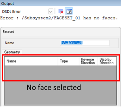
DSDL Error : Faceset_Name has no faces.
If the message <Faceset_Name> has no faces appears in
the DSDL Error tab of the Output window,
the analysis may fail to run.
This error occurs when faces within a Faceset are removed during Parasolid conversion. Create a new Faceset and replace the problematic Faceset with it.
Journal files from legacy files do not work
Due to changes in face, edge, and curve IDs, journal files saved from legacy files may not function correctly. Update the IDs in the journal file or regenerate the journal.
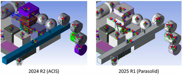
Body color not retained
When opening legacy files in 2025 R1, body colors may not be retained. Reset the body color in the body properties.
Dimension Limits on Bodies
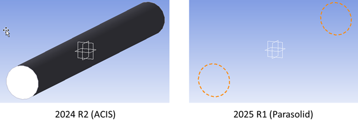
Issues occur if any body exceeds 1 km in any dimension (x, y, or z). Bodies must fit within a space where each dimension is 1 km or less.
When using the Stride Convert engine to convert legacy files, an error message such as STR-ERR(10003): The geometry in the file exceeds the size limit of the Parasolid. Conversion fails with Stride Convert. may appear, and the conversion will fail.
Using other conversion engines may succeed, but the body may appear distorted, or unexpected issues may arise.
When using the Import CAD feature to import CAD files or the Create Cylinder, Sphere, Box, and similar features to generate bodies, exceeding the size limit may result in improper geometry display.
Solver Errors During Analysis: NURBS Surface Vertex UV Mapping Issues
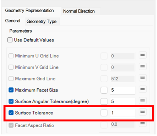
The solver may produce the error FAILURE FINDING VERTEX INITIAL UV IN NURBS SURFACE. This occurs when the solver cannot locate the UV coordinates of a vertex on a NURBS surface within a Faceset. Adjusting the Surface Tolerance in the Faceset properties to better align the geometry with the CAD model may resolve this issue. If the problem persists, consider re-importing the CAD geometry and reconfiguring the Faceset properties.
Reverse Direction of Faces in Facesets Causing Contact Issues (new in 2025 R1 SP2)
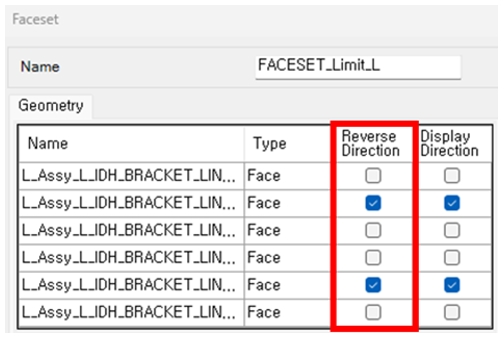
When using the Stride Convert engine, some faces within Facesets may be converted with the Reverse Direction option checked, resulting in incorrect normal directions. If the normal direction is incorrectly set, it may lead to issues where contact does not occur as expected. Verify the normal directions in the Faceset properties by checking the Display Direction option to ensure the normal direction is correctly set, and make adjustments if necessary.
Solid Geometry Converted to Shell Geometry (new in 2025 R1 SP2)
Models that failed to load with other conversion engines may be successfully converted using Stride Convert. However, in some cases, solid geometries may be converted to shell geometries because they cannot be identified as closed geometry due to CAD defects. To address this, fix the CAD defects using CAD tools, then re-import the corrected file.