


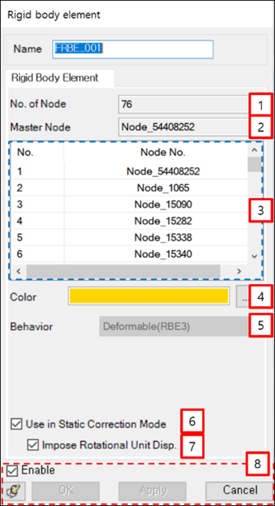
From the Rigid body element properties dialog, the nodes and their parameters can be displayed as shown in the figure and table below.
| Parameter | Symbol | Description | Dimension (Range) |
|---|---|---|---|
| 1. No. of Node | N/A | Displays the number of nodes in the Rigid body element. | N/A |
| 2. Master Node | N/A | Displays the Master node ID. | N/A |
| 3. List of Nodes | N/A | Displays the node IDs in the Rigid body element. | N/A |
| 4. Color | N/A | Used to set the color of the Rigid body element. | N/A |
| 5. Behavior | N/A | Displays the Rigid body element’s behavior. This can be either or . | N/A |
| 6. Use in Static Correction Mode | N/A | Used to set the interface node during body eigenvalue analysis. When this option is selected, the master node is treated as an interface node which can be used as a connector for a Modal FE Body. | N/A |
| 7. Impose Rotational Unit Disp. | N/A | This option is automatically selected when Use in Static Correction Mode (above) is selected. Clear the option to exclude the rotational mode of the master node for a Modal FE Body. | N/A |
| 8. Control buttons | N/A | If all necessary parameters are set, these buttons are enabled. For more information about the control buttons, refer to Entity Properties Access and Modification. | N/A |