


The pin of a Cycloidal Reducer is shared for two or more cycloid discs. Pins are installed to the RBE of the housing by the constraint (Revolute joint).

After creating a Cycloidal Reducer entity, you should set up the cycloid pin in the Assembly Manager.
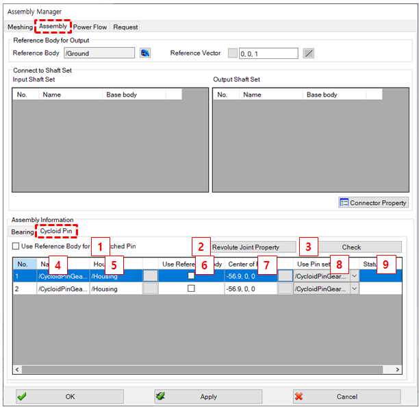
Figure 14.305: Parameters for Cycloid Pin setup
| Parameter | Description | Dimension |
| 1. Use Reference Body for Unmatched Pin |
Selected : Pins are assembled with the reference body Cleared : Pins are assembled with the RBE of the housing. | N/A |
| 2. Revolute Joint Property | Use to set the property of the revolute joint which is created between housing and pin. | N/A |
| 3. Check | Use to check the mating condition between cycloid disc and pin. | N/A |
| 4. Cycloid pin list | Show the cycloid pin lists. | N/A |
| 5. Housing | Show the housing where the pin should be assembled. You can change the selection here. | N/A |
| 6. Use reference body | If you select Use Reference Body for Unmatched Pin this option is also selected. You can clear this option for each list item. | N/A |
| 7. Center of Pin | Use to set the center position of the pin set. | N/A |
| 8. Use pin set | Select the pin set. When you need to share the pin for multi cycloid gears, you can select the required cycloid pin. | N/A |
| 9. Status | Show the whether assembly is possible or not (this status is only for the cycloid pin) | N/A |